7 Connect the system fan cable to the connector on the system board.
8 Close the front panel door.
9 Install the:
a Memory module
b Optional M.2 PCIe SSD
c Expansion card
d SD card reader
e Processor
f Heat sink assembly
10 Close the front panel door.
a Back cover
11 Follow the procedure in After working inside your computer.
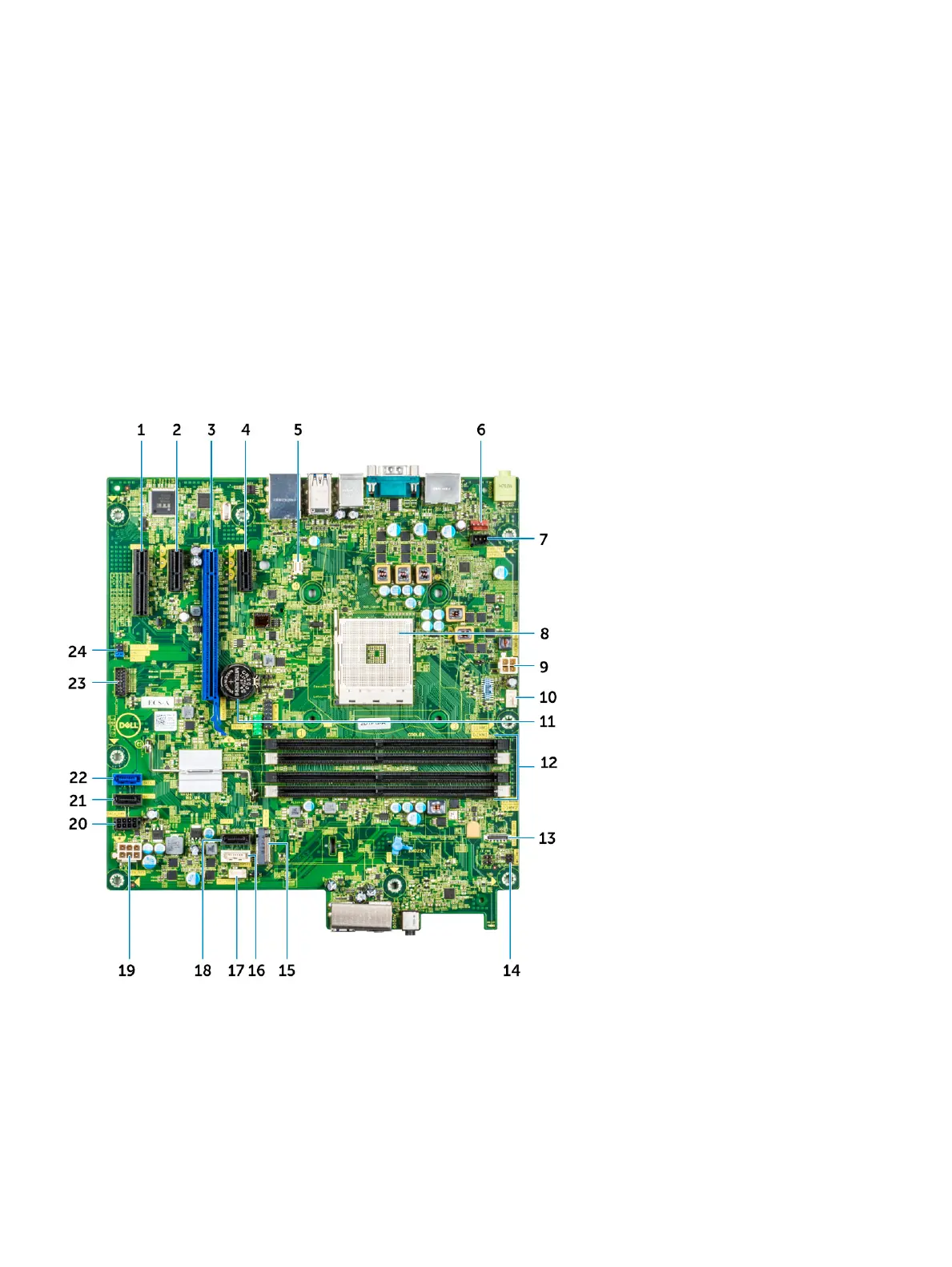
System board layout
This chapter explains about the motherboard's layout with name and location of its connectors.
1 PCI-eX4(wire x2) Connector (Slot4) 2 PCI-eX1 Connector (Slot3)
3 PCI-eX16(wire x8) Connector (Slot2) 4 PCI-eX1 Connector (Slot1)
5 VGA Daughter Board Connector (VGA) 6 Intrusion Switch Connector (INTRUDER)
7 System Fan Connector (FAN_SYS) 8 Processor Socket
9 CPU Power Connector (ATX_CPU) 10 CPU Fan Connector (FAN_CPU)
46 Disassembly and reassembly