System board
System board callouts - 7000 Small Form Factor
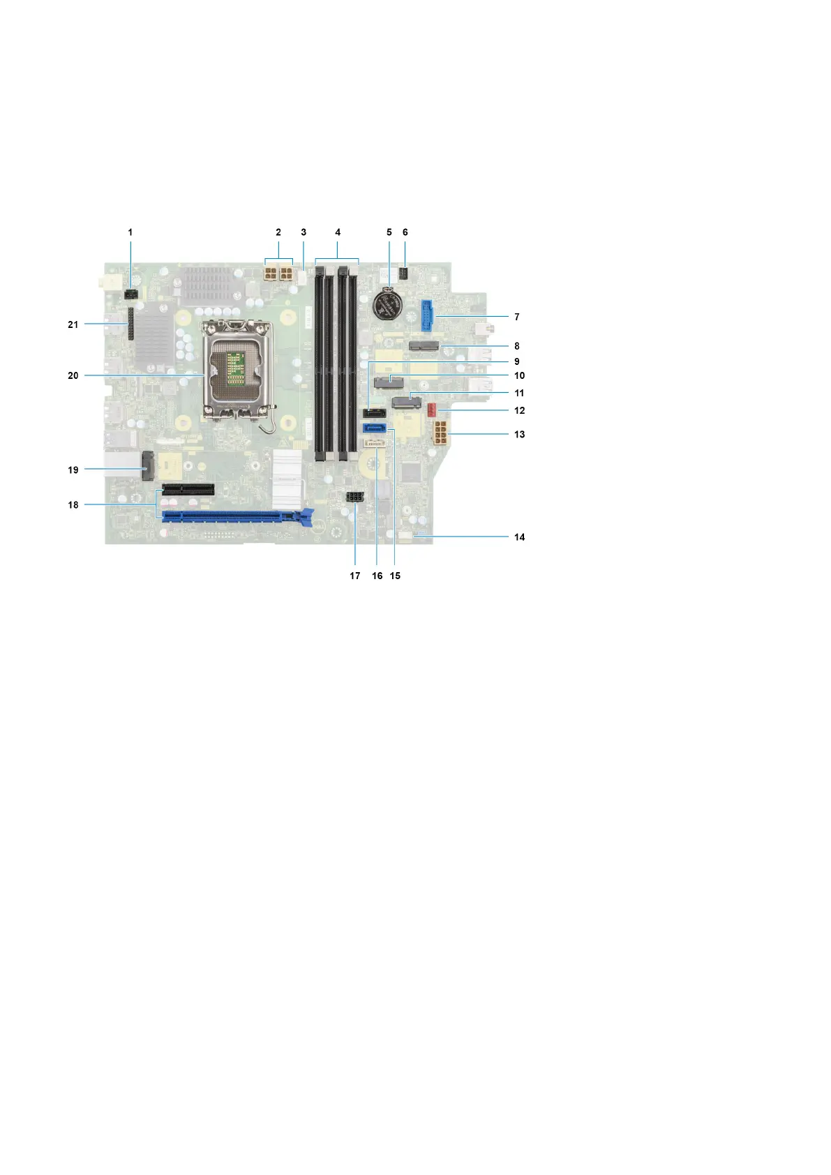
The following image indicates the slots and connectors on your system board.
1. Intrusion switch cable
2. Processor-power cables
3. Processor fan connector
4. UDIMM slots
From the left (a>b>c>d):
DIMM 3
DIMM 1
DIMM 4
DIMM 2
5. Coin-cell battery socket
6. Power-button cable
7. SD-card reader slot
8. M.2 WLAN slot
9. Hard-drive data cable (SATA 0)
10. M.2 2230 solid-state drive slot
11. M.2 2230/2280 solid-state drive slot
12. Chassis-fan cable
13. ATX system power connector
14. Internal-speaker cable slot
15. Hard-drive data cable (SATA 1)
16. Optical-drive/hard-drive data cable (SATA 2)
17. SATA power cable
18. a. PCIe x16 slot (SLOT 2)
b. PCIe x4 slot (SLOT 4)
c. PCIe x4 slot (SLOT 1)
72
Removing and installing components