1036 Configuring VRRP
VRRP Configuration Example
This section contains the following VRRP examples:
• VRRP with Load Sharing
• VRRP with Route and Interface Tracking
VRRP with Load Sharing
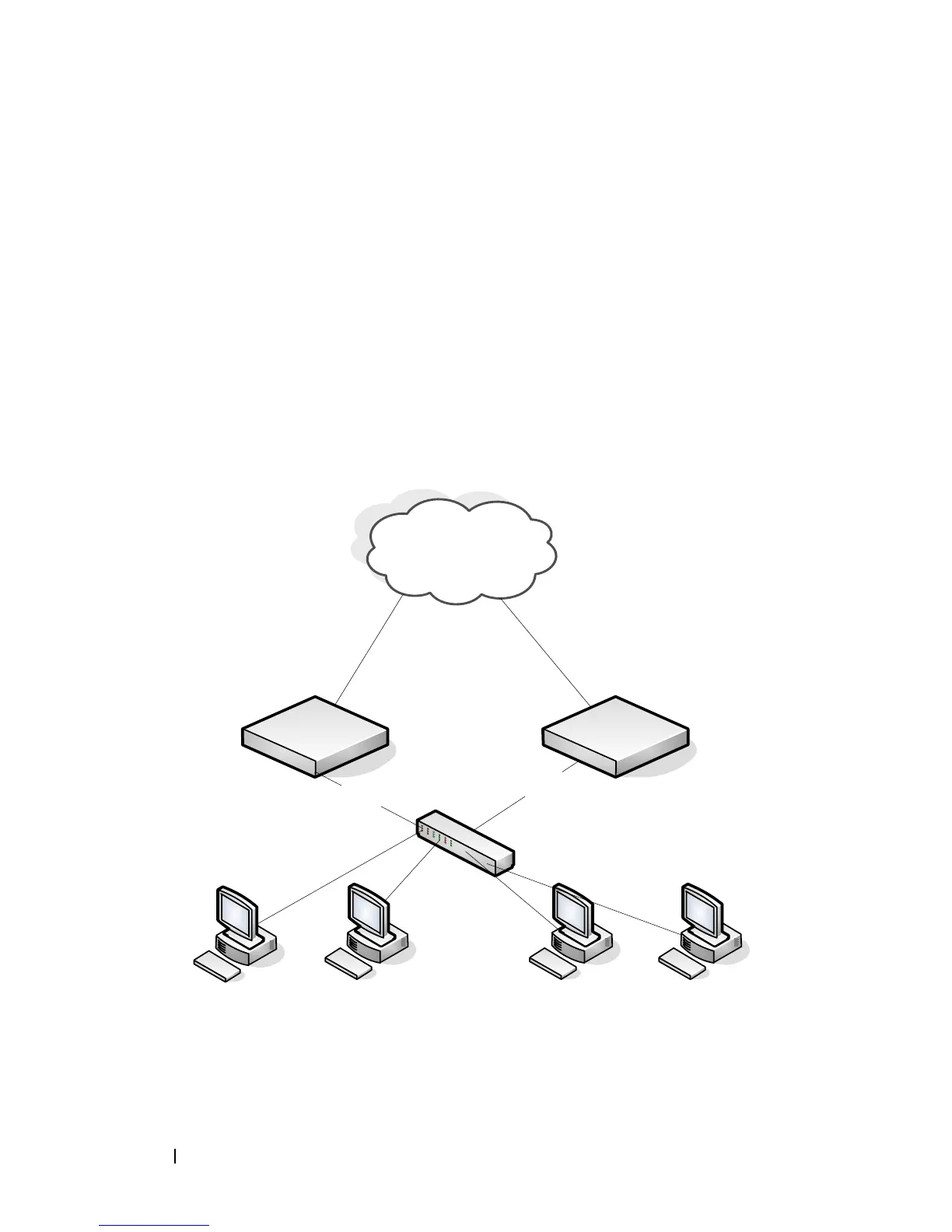
In Figure 36-9, two L3 PowerConnect switches are performing the routing for
network clients. Router A is the default gateway for some clients, and Router
B is the default gateway for other clients.
Figure 36-9. VRRP with Load Sharing Network Diagram
`
Router A Router B
` ` `
L2 Switch
External Network
VLAN 10
192.168.10.1
VLAN 10
192.168.10.2
Default Gateway
192.168.10.1
Default Gateway
192.168.10.1
Default Gateway
192.168.10.2
Default Gateway
192.168.10.2
VRID 10: 192.168.10.1
VRID 20: 192.168.10.2
 Loading...