904 Configuring IP Routing
IP Routing Configuration Example
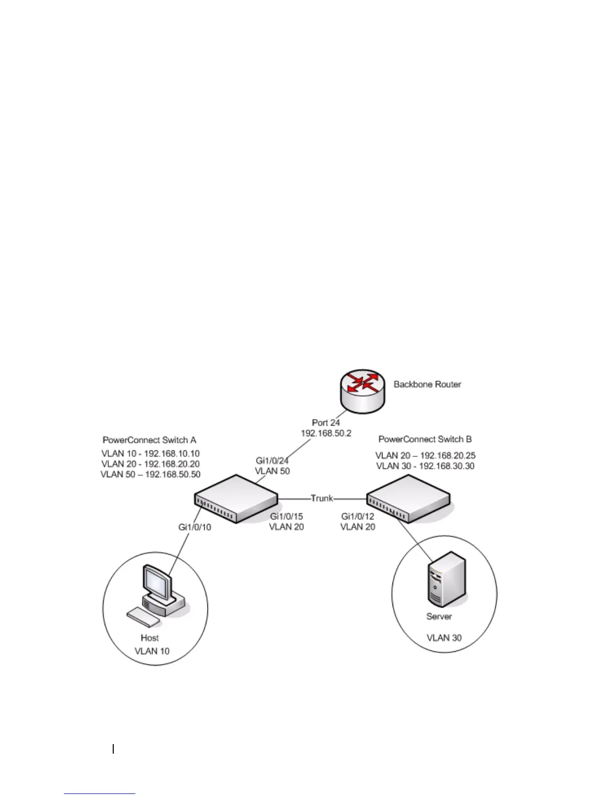
In this example, the PowerConnect switches are L3 switches with VLAN
routing interfaces. VLAN routing is configured on PowerConnect Switch A
and PowerConnect Switch B. This allows the host in VLAN 10 to
communicate with the server in VLAN 30. A static route to the VLAN 30
subnet is configured on Switch A. Additionally, a default route is configured
on Switch A so that all traffic with an unknown destination is sent to the
backbone router through port 24, which is a member of VLAN 50. A default
route is configured on PowerConnect Switch B to use Switch A as the default
gateway. The hosts use the IP address of the VLAN routing interface as their
default gateway.
This example assumes that all L2 VLAN information, such as VLAN creation
and port membership, has been configured.
Figure 32-13. IP Routing Example Topology
 Loading...