EasyManuals Logo

Dell PowerSwitch S4048-ON User Manual

Dell PowerSwitch S4048-ON
42 pages
To Next Page IconTo Next Page
To Previous Page IconTo Previous Page
Page #31 background imageLoading...
Page #31 background image
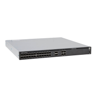
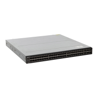
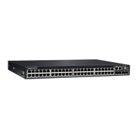
Fan module installation
The fan modules in the S4048ON are field replaceable.
Module slot 1 is on the left side of the chassis, module slot 2 is in the middle of the chassis, and module slot 3 is on the right side
of the chassis.
CAUTION: DO NOT mix airflow directions. All fans must use the same airflow directionreverse or normal.
1. Take the fan module out of the shipping box.
2. Use the grab handle to slide the module into the bay.
Fan module replacement
CAUTION: Complete steps 2 and 3 within one minute, or the switch turns off.
1. Use the red-marked grab handle to slide the fan module out of the bay.
2. Use the red-marked grab handle on the replacement module to slide it into the bay.
3. Ensure that the module is secure.
Fans 31

Table of Contents

Questions and Answers:

Question and Answer IconNeed help?

Do you have a question about the Dell PowerSwitch S4048-ON and is the answer not in the manual?

Dell PowerSwitch S4048-ON Specifications

General IconGeneral
Switching Capacity1.44 Tbps
AirflowFront-to-back or back-to-front
ManageableYes
Total Number of Network Ports54
Uplink Port6 x 40GbE QSFP+
Number of 40 Gigabit Ethernet Ports6
Number of 10 Gigabit Ethernet Ports48
Media Type SupportedOptical Fiber, Twisted Pair
Ethernet Technology10 Gigabit Ethernet, 40 Gigabit Ethernet
Layer SupportedLayer 2, Layer 3
Form FactorRack-mountable
Operating Temperature32 °F to 104 °F (0 °C to 40 °C)
Power SupplyDual, hot-swappable
Dimensions1.7 inches
Product TypeLayer 3 Switch
Port/Expansion Slot Details48 x 10GbE SFP+, 6 x 40GbE QSFP+
Network Technology40GBase-X
Input Voltage100-240 VAC
Height1.7 inches
Width17.3 inches
Ports48 x 10GbE, 6 x 40GbE
Weight24.5 lbs

Related product manuals