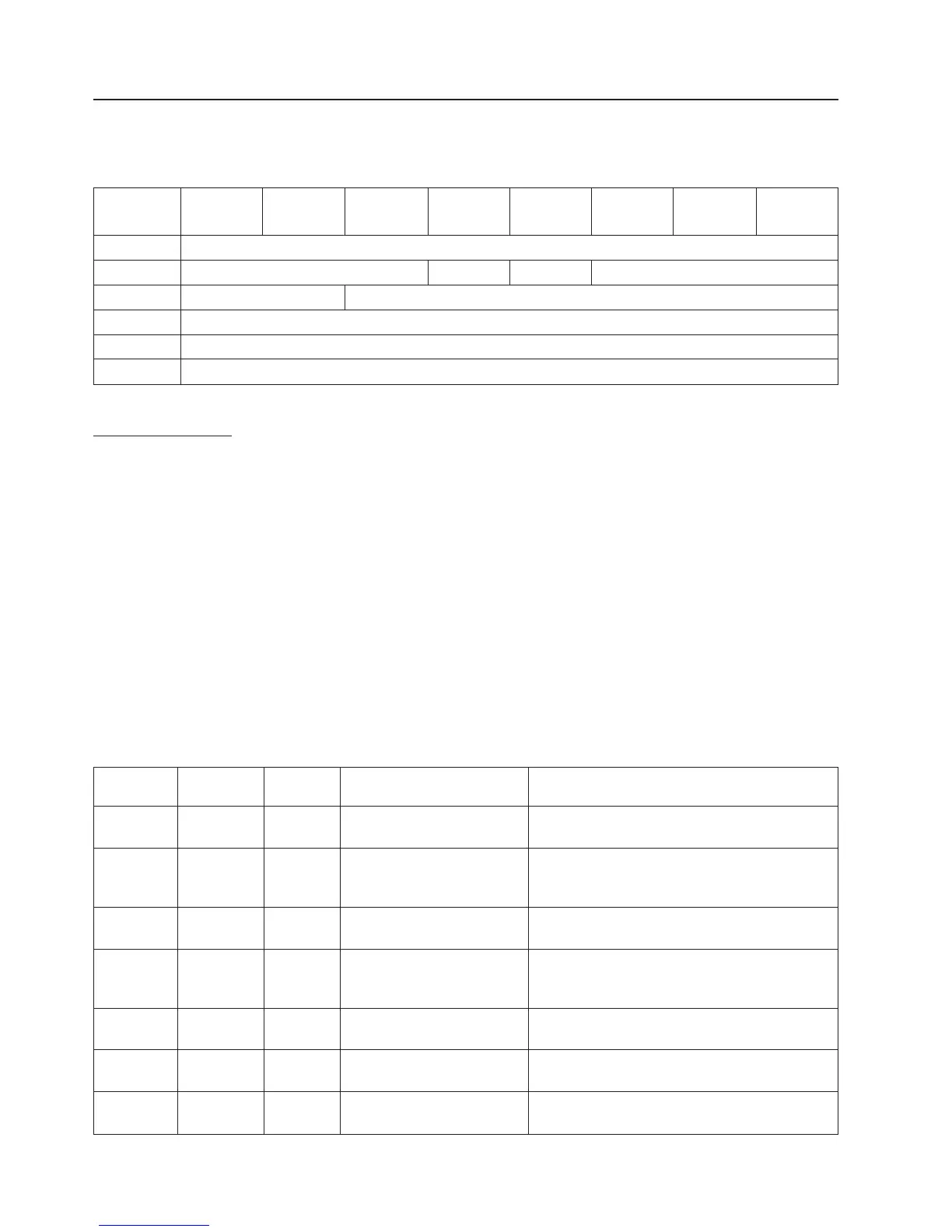
MODE SENSE 6 (1Ah)
The MODE SENSE (6) command provides a means for a device server to report parameters to an
application client. It is a complementary command to the MODE SELECT (6) command.
Bit 7 6 5 4 3 2 1 0
Byte
0 Operation Code (1Ah)
1 LUN Reserved DBD Reserved
2 PC Page Code
3 Subpage Code
4 Allocation length
5 Control
Field descriptions:
DBD: The Disable Block Descriptors bit specifies if the media changer may return block descriptor after
the Parameter List Header. The media changer does not support block descriptors, therefore this
bit is ignored.
PC: The Page Control field defines the type of mode parameter values to be returned in the mode
pages.
00b Report Current Values (equal to default values if no pages previously saved)
01b Report changeable values
10b Report Default Values
11b Report Saved Values (equal to default values if no pages previously saved)
Page Code:
The page code defines which pages should be returned. See next table. A Initiator can request
one or all mode sense pages. Each response includes a four bytes for the Parameter List Header,
followed by the specified number of bytes for each page:
Page Code Subpage
Code
Number
bytes
Page Name Page Description
00h 00 4 Parity Page Provides a means to read out the setting for
maximum number retries on parity errors.
0Ah 01h 32 Control Extension Page Provides a means to read out the capabilities of
the SET TIMESTAMP and REPORT
TIMESTAMP commands.
1Ch 00h 12 Tape Alert Page Allows the host to see what mechanism is used
to report Tape Alert events.
1Dh 00h 20 Element Address
Assignment Page
Provides a means to read the SCSI element
address assignments and respective element
ranges.
1Eh 00h 4 Transport Geometry Page Provides a means to read the specifics about
the Medium Transport Element.
1Fh 00h 20 Device Capabilities Page Provides a means to read the library's
capabilities.
20h 00h 8 Event Filter Page (Vendor
Specific)
Provides a means to read out the current
selected event filter settings.
3-30 TL2000 and TL4000 SCSI Reference
 Loading...