9. Remove the secondary memory.
10. Remove the WWAN card.
11. Remove the WLAN card.
12. Remove the keyboard lattice.
13. Remove the keyboard.
14. Remove the primary memory.
15. Remove the heat-sink assembly.
16. Remove the inner frame.
17. Remove the GPU power cable.
18. Remove the GPU card.
19. Remove the system board.
20. Remove the display assembly.
21. Remove the speaker.
22. Remove the display bezel.
23. Remove the display panel.
24. Remove the P-sensor board.
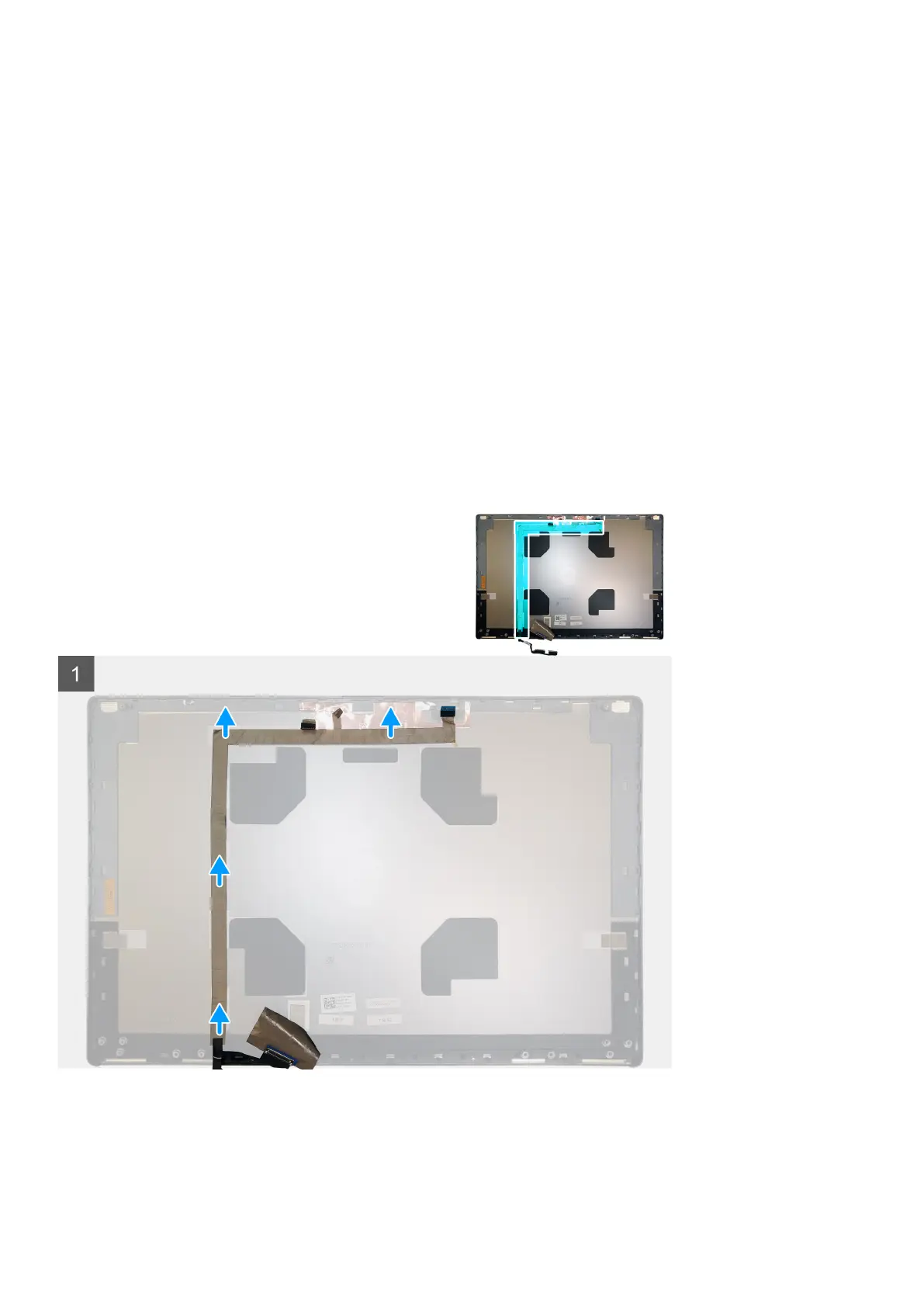
About this task
The figure indicates the location of the display cable and provides a visual representation of the removal procedure. Images to be uploaded
in the next review cycle.
Steps
1. Peel the adhesive tape covering the camera module.
2. Disconnect the display cable from the camera module.
3. Peel the display cable from the display cover and unroute the cable from the routing channels
Disassembly and reassembly
93