Fan LEDs
• Solid green—fan function is normal.
• Flashing yellow—there is a fan fault.
• O—fan is o.
Fan module installation
The fan modules in the S4100–ON Series (S4128F-ON and S4148F-ON) switch are eld replaceable.
When looking at your switch, Slot 1 is on the left side of the switch and Slot 4 is on the right side of the switch.
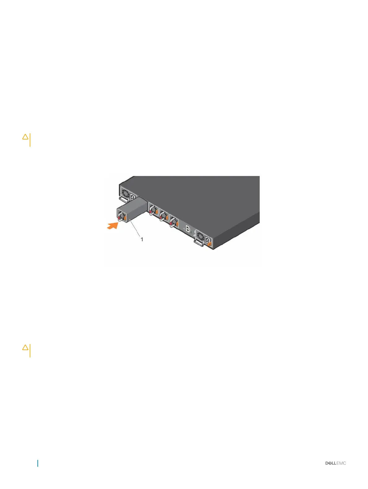
CAUTION: DO NOT mix airow directions. All fans must use the same airow direction—reverse or normal. If you mix the airow
direction, to avoid overheating the switch, correct the mixed airow.
1 Take the fan module out of the shipping box.
2 Slide the module into the bay.
Figure 20. S4100–ON Series fan modules installation
1
Fan unit
Fan module replacement
To request a hardware replacement, see Dell EMC support.
CAUTION
: Complete the following steps within one minute or the switch temperature could rise above safe thresholds and the
switch could shut down:
1 Slide the fan module out of the bay.
2 Slide the replacement module into the bay.
34
Fans
 Loading...