Steps
1. Slide the system board at an angle with the rear external ports aligned to their respective openings of back panel at the rear
of the chassis.
2. Place the system board onto the chassis and ensure the front I/O-ports are placed into the front I/O-slots on the chassis.
3. Replace the seven screws (#6-32) and the screw (#6-32x3.8) that secure the system board to the chassis.
4. Route and connect the following cables to the system board. See the system-board components for more information about
the respective connectors of the following cables:
● hard-drive and optical-drive power cable
● optical-drive data cable
● hard-drive data cable
● system-board power cable
● power-button cable
● processor-power cable
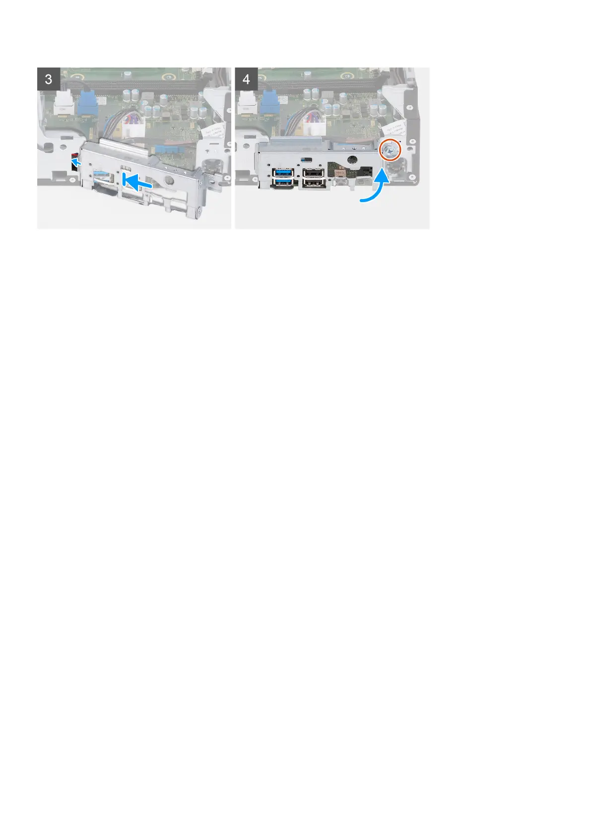
5. Place and align the front I/O-bracket with I/O slot on the chassis.
6. Replace the screw (#6-32) that secures the front I/O-bracket to the chassis.
Next steps
1. Install the processor.
2. Install the fan and heat-sink assembly.
3. Install the fan shroud.
4. Install the media-card reader.
5. Install the coin-cell battery.
6. Install the wireless card.
7. Install the M.2 2230 solid-state drive or M.2 2280 solid-state drive, which is applicable.
8. Install the memory.
9. Install the HDD and ODD cage.
10. Install the 3.5-inch hard drive.
11. Install the front cover.
12. Install the left-side cover.
13. Follow the procedure in After working inside your computer.
52
Removing and installing components