ASDA-M Chapter 3 Wiring
Revision December, 2014 3-25
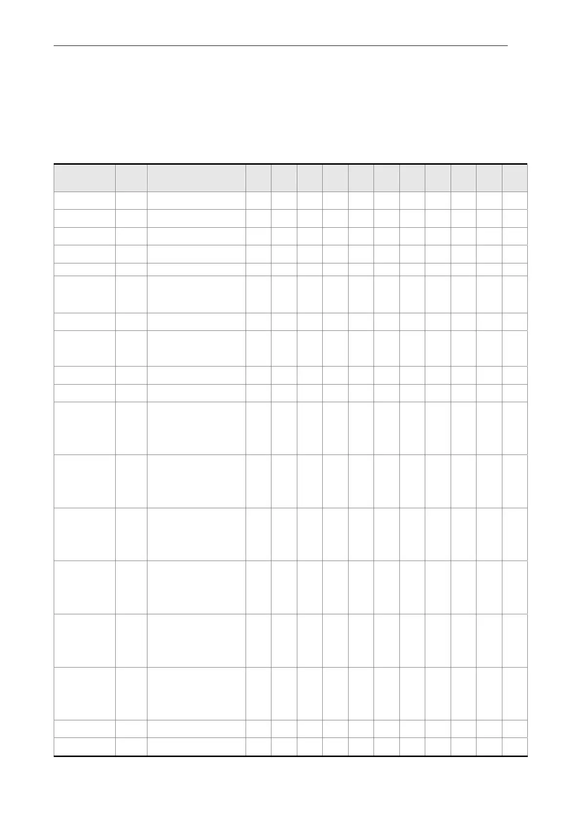
The default setting of DI and DO in each operation mode is shown as the followings.
Please note that the following table neither detail the information as the previous one nor
show the Pin number of each signal. However, each operation mode is separated in
different columns in order to avoid the confusion.
Table 3.1 Default Value of DI Input Function
Symbol
DI
Code
Input Function PT PR S T Sz Tz
PT
S
PT
T
PR
S
PR
T
S
T
SON 0x01 Servo on DI1 DI1 DI1 DI1 DI1 DI1 DI1 DI1 DI1 DI1 DI1
ARST 0x02 Alarm reset DI5 DI5 DI5 DI5 DI5 DI5
GAINUP 0x03 Gain switch
CCLR 0x04
Pulse clear
DI2 DI2 DI2
ZCLAMP 0x05 Zero speed clamp
CMDINV 0x06
The input command
will be in reverse
direction.
Reserved 0x07 Reserved
CTRG 0x08
Internal position
command triggered
DI2 DI2 DI2
TRQLM 0x09
Torque limit
DI2 DI2
SPDLM 0x10
Speed limit
DI2 DI2
POS0 0x11
Internal position
command selection
0
DI3 DI3 DI3
POS1 0x12
Internal position
command selection
1
DI4
POS2 0x13
Internal position
command selection
2
POS3 0x1A
Internal position
command selection
3
POS4 0x1B
Internal position
command selection
4
POS5 0x1C
Internal position
command selection
5
STOP 0x46 Motor stops
SPD0 0x14 Speed command DI3 DI3 DI3 DI4 DI3
 Loading...


