Introduction of E-Cam Operation ASDA Series Application Note
2-36 March, 2015
360
o
= 2 W + 2Acc + 2S +Y
S
o
^S) * 360 / (P5-82)
S
o
S
P5-82=72
1234
10
o
20 40
o
80
o
Y
3
360 = 2 W + 2Acc + 2S
o
+Y
S ^S) * 360 / (P5-82)
S
S
P5-82=72
1234
10 20
o
40 80
Y
3
=(=(22
WW AccAcc
S
°
S
AccAcc S
°
WW
360
°
360
°
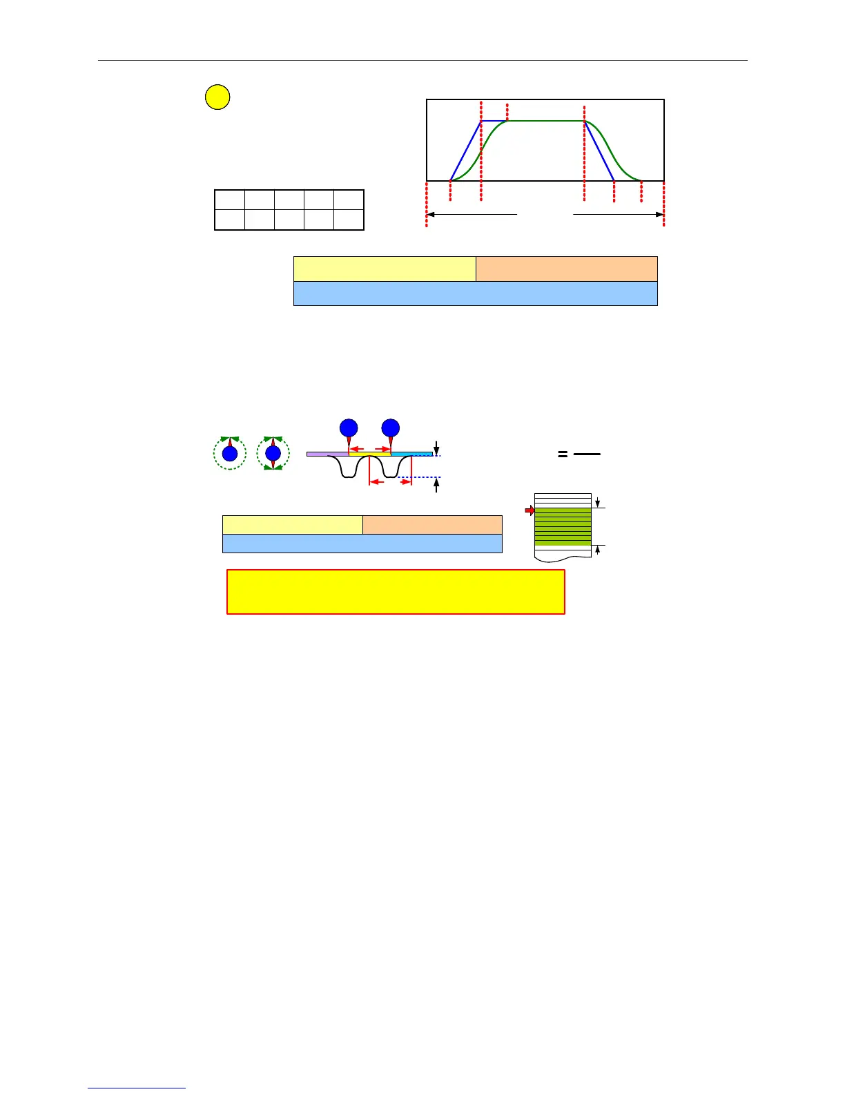
16 bits (S level, 1~4) 16 bits (W ,0~170º)
P5-93
32 bits (Y, Constant Speed Area, 0~330º, Decimal)
P5-94
P5-93.H (Hex.) P5-93.L (Hex.)
Figure 2.52 Setting Proportion of Each Speed Area of Rotary Shear Curve when Using Macro 7
Since the waiting area is adjustable, there are more limitations when creating E-Cam curve
by Macro 7. See Figure 2.53.
Figure 2.53 Limitations of Creating E-Cam Curve for Rotary Shear by Macro 7
Step 4: See Figure 2.54. Figure out the mechanical specifications and enter relevant
parameters. The required specification data is the same as that needed when creating
E-Cam curve for rotary shear. Users may use HMI to enter the data or use HMI or PLC to
calculate relevant values and download them to the servo drive.
16 bits (S level, 1~4) 16 bits (W ,0~170º)
P5-93
32 bits (Y, Constant Speed Area, 0~330º, Decimal)
P5-94
P5-93.H (Hex.) P5-93.L (Hex.)
360º = 2W + 2Acc + 2Sº +Y
a
a
a
A
A
a
W’ = 180 + 360/(P5-82) - 360/R + (P5-94)/2
R (Length Ratio)
A
a
W < W’, Error Code F07A, enlarge waiting zone or
narrow constant speed area.
W = W’, The starting speed of the curve = 0.
W > W’, The starting speed of the curve > 0.
P5-82 = 30~72
Data Array

 Loading...


