ASDA Series Application Note Application Examples
March, 2015 3-49
From the above Figure 3.3.12, the label length brought by each roller revolution is π*5 cm =
15.708 cm. To meet the requirement of maximum 23 cm, the curve must be longer than 23 cm
since the acceleration / deceleration time should be left. 23 cm is the traveling distance that
master axis and camshaft axis operates at the same speed. Then, to create the E-cam curve
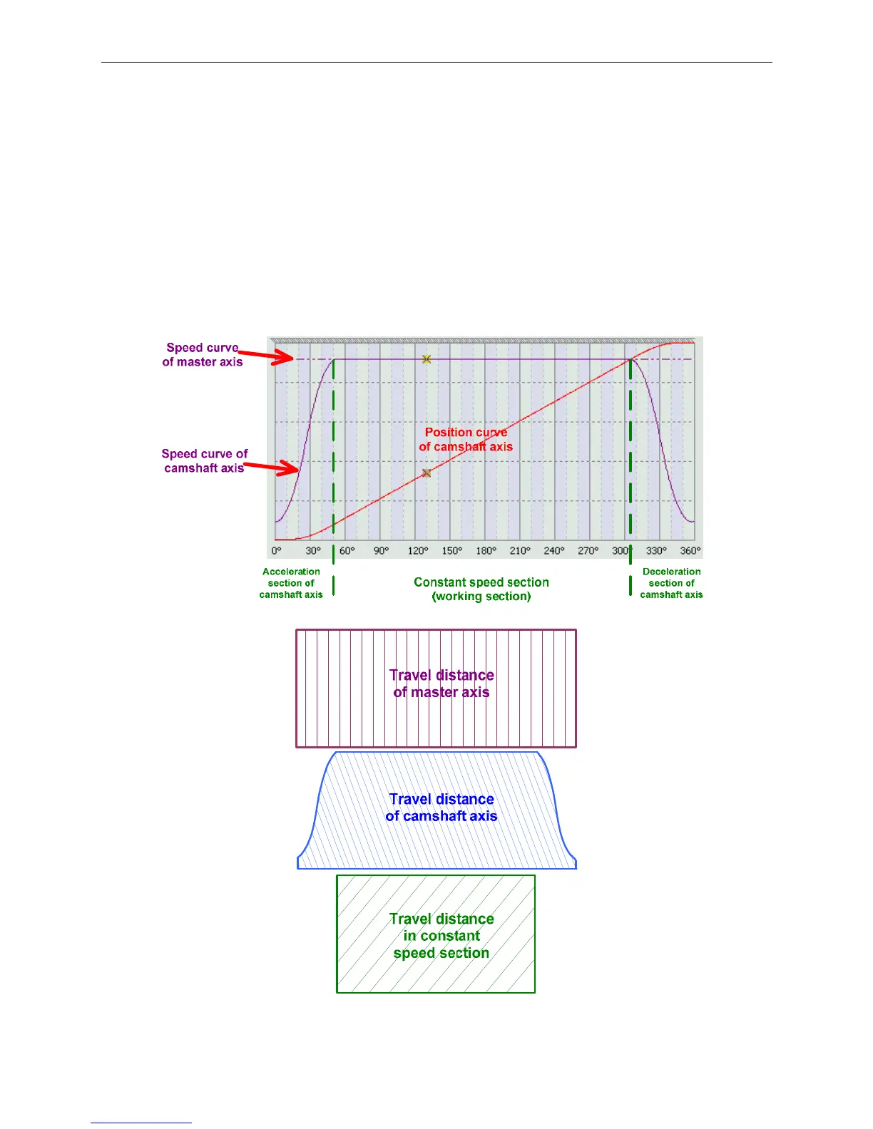
based on this value. In Figure 3.3.13, master axis is at constant speed while camshaft axis has
acceleration and deceleration. Thus, within the same time, considering the acceleration and
deceleration time of camshaft, master axis travels farther than camshaft axis. In actual operation,
camshaft axis must be enabled in advance so as to complete labeling in constant speed section.
That is to say, from Figure 3.3.13, the traveling distance is Constant Speed Area < Camshaft axis
< Master axis. The creation of E-cam curve will be introduced in the following parts.
Figure 3.3.13 E-cam curve
Through the setting of electronic gear ratio, system not only can consist with the command
 Loading...


