Application Examples ASDA Series Application Note
3-50
March, 2015
resolution, but increase its readability. In this example, the traveling distance for each camshaft
axis resolution is π*5 cm =15.708 cm. In order to make the data more readable, users can set
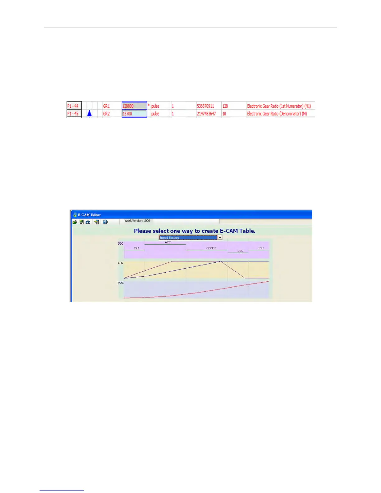
157080PUU for each cycle the camshaft travels, which is 0.001 mm per PUU. Thus, set P1-44
to 128000 and P1-45 to 15708. When P5-19 is set to 1 (E-cam curve scaling), the relative pulse
command is (157080PUU / 15.708 cm) = 1000 PUU/mm of each mm on camshaft axis. See
Figure 3.3.14.
Figure 3.3.14 E-gear setting
If users desire to create a curve of 31.416 cm (314.16 mm), then 314.16 (mm)* 1000(PUU/mm) =
314160 PUU.
In ASDA-A2, Speed Section is used to create E-cam table. Please refer to the following steps.
a. Select the way to create E-cam table
Select Speed Section to create E-cam table. See Figure 3.3.15.
Figure 3.3.15 Select Speed Section
b. Setup the actual machine dimensions
Master axis is 10.185916 Pulse/mm and camshaft axis is 1000 PUU/mm. When creating E-cam
curve, the system will refer to the above simulation data. Please make sure the information is
correct, which is the pulse number and PUU the system needs when master axis and camshaft
axis moves 1 mm. See Figure 3.3.16.
 Loading...


