ASDA Series Application Note Application Examples
March, 2015
3-79
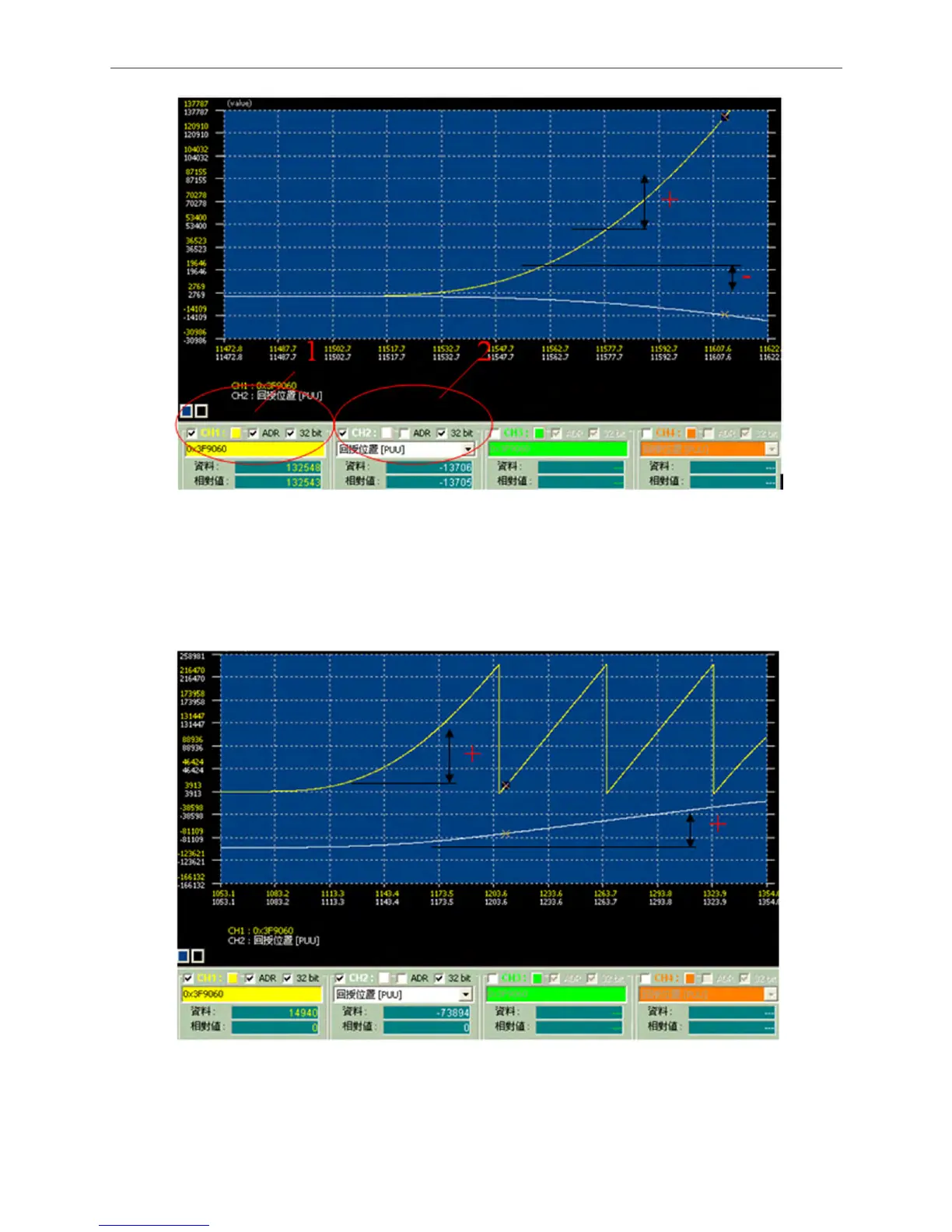
Figure 3.5.14 The Phases of Feedback Pulse in the Opposite Direction
4. If the setting is correct, the signal will be the same as shown in the figure below; the increasing
amount is in the same direction. (The zigzag signal shown in yellow is normal because value
resetting is done to avoid overflow.)
Figure 3.5.15 The Monitoring Phase of Feedback Pulse is Identical
5. Then, connect the PC scope to the other servo drive and make sure the phase of feedback
pulse is correct.

 Loading...


