Application Examples ASDA Series Application Note
3-80
March, 2015
Step 6: Activate the synchronous control
Activate the synchronous control via P1-74; set digit in ones to 2, the synchronous control of
gantry will be activated.
Step 7: Trial runs
1. Let gantry function remain in pause so as to assure the mechanism is safe when
adjusting parameters.
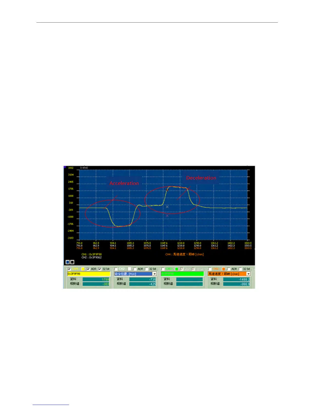
2. After setting the bandwidth to a proper value (adjust from small to large), let host controller
issue position commands and observe the position deviation and synchronization of two
axes via PC scope. Same as the setting in figure 3.5.16, select CH1, ADR, and 32 bit and
then enter address 0x3F9F98; this would be the position deviation between both axes and
the unit is pulse (using full closed-loop resolution P1-72 as a basis). If the deviation of two
axes exceeds the setting value, alarm will occur. In general, there is no chance that the
loading conditions of two axes are exactly identical, the acceleration/deceleration process
will thus leading to a rather large position deviation.
Figure 3.5.16 Monitoring Position Deviation of Gantry
3. When conducting trial runs, be sure to adjust the parameters to proper values; the bandwidth
settings of the two controllers has to be identical so as to avoid alignment deviation due to
their different response time. When executing the acceleration/deceleration command from
the host controller, the position deviation has to be within the setting range of P1-73;
otherwise, the alarm will occur.

 Loading...


