ASDA Series Application Note Application Examples
March, 2015 3-81
Step 8: Synchronizing test and parameters adjustment
1. Be sure to complete the steps described above. Then, please use parallel connection to
connect the gantry mechanism between two motors and then start testing the gantry.
2. Please do Step 2 mentioned above again. Re-estimate the system inertia; otherwise, the
system setting will not be accurate and unable to work properly. If the mechanism is not
symmetric, inertia ratio of two axes would be different.
3. The system has to be in protection of miss-synchronization and the deviation value of P1-73
must be absolutely correct.
4. Basically, the bandwidth settings of both servo drive and gantry synchronous control has to
be identical. The bandwidth of the servo drive can be calculated and set in Auto Gain Tuning
via ASDA Soft; Gantry bandwidth can be set via P2-57 (The Bandwidth of Synchronous
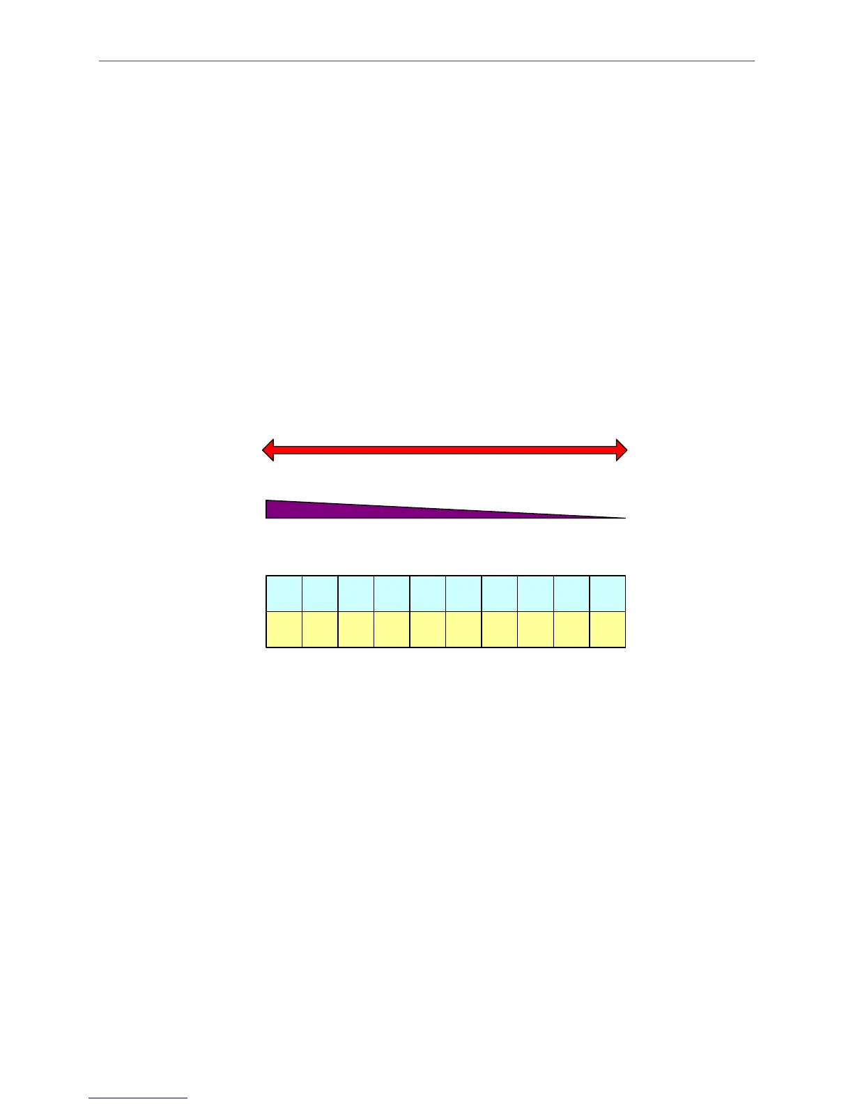
Control). See Figure 3.5.17.
Figure 3.5.17 Setting Up Bandwidth Proportion
Regarding the synchronous bandwidth, users have to set P2-57 (The bandwidth of Synchronous
Control) only. The system will automatically calculate the value of P2-54~P2-56 (the related
parameters of synchronous control). When the bandwidth setting of synchronous control is wider
than the bandwidth of servo drive, the following result between two motors is better. (However,
the following for the host controller will be relatively worse). Please note that when “Bandwidth of
synchronous control + Bandwidth of the servo drive> Permitted bandwidth of the system”, it is
easier to cause resonance. If bandwidth cannot be increased in order to achieve better following,
please try to increase the value of P2-55 (Integral Compensation to Synchronous Position).
However, if the value of P2-55 is set too high, system vibration will occur. When deciding the
bandwidth, be sure that the setting value of P2-25 is much bigger than the bandwidth setting;
otherwise, the result might not be satisfactory and system might become unstable if worse.
When adjusting the bandwidth of the synchronous control, start from small to large.
The synchronous control of the gantry is shown in Figure 3.5.18.
Error tolerance
set in P1-73
big small
Bandwidth
proportion
100 % 10 %
Bandwidth proportion = Servo bandwidth / (Servo
bandwidth + synchronous bandwidth)
10
0%
0
%
90
%
10
%
80
%
20
%
70
%
30
%
60
%
40
%
50
%
50
%
40
%
60
%
30
%
70
%
20
%
80
%
10
%
90
%
Servo
bandwidth
Synchronous
bandwidth

 Loading...


