ASDA Series Application Note Chapter 4 Application Techniques
March, 2015 4-31
Pulse number of master axis after
rotating a cycle: (P5-84/P5-83) = L
Master axis position (X)
Slave axis
position (Y)
Current
engaged
position
Alignment target
position P5-96
Alignment
correction value
= Y_Diff
*P5-93.UZ is able to limit the max. correction rate. The alignment target position ★ will be
different from P5-96.
| aignment target position★ – current engaged position| / L <= P5-93.UZ %
*DI time delay compensation can be set via P5-94, it can correct the error caused by different
operation speed.
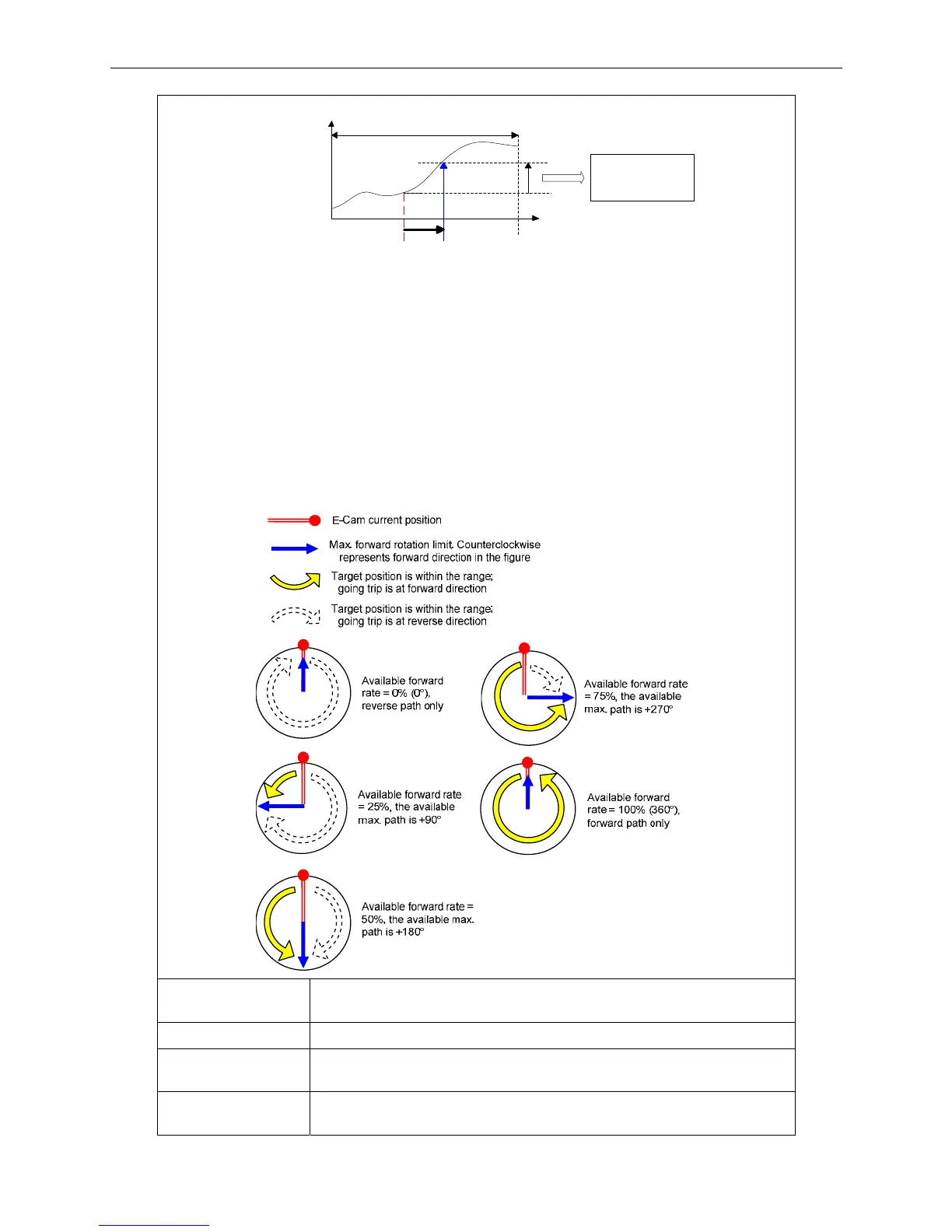
When E-Cam moves from current position to the target one, it can rotate at forward or reverse
direction. Due to the cyclic operation, it can reach the target position either at forward or reverse
direction. However, the moving distance between both is usually different. Use available forward
rate to plan the timing of forward and reverse rotation.
*Available forward rate: The available max. proportion of forward path
Failure code F0E1h When executing this macro, E-Cam is not engaged. E-Cam has to
engage to execute alignment correction.
Failure code F0E2h The setting value of P5-93.YX (PR number) exceeds the range: 0 ~ 0x3F
Failure code F0E3h The setting value of P5-93.UZ (Max. alignment correction rate) exceeds
the range: 0 ~ 0x64 (%)
Failure code F0E4h The setting value of P5-94 (DI delay time compensation) exceeds the
range: -10000 ~ +10000
 Loading...


