ASDA Series Application Note Introduction of E-Cam Operation
March, 2015
2-17
appropriate area number of E-Cam in data array. Data array is able to store max 800
data. Users need to pay special attention to the setting limit if desire to store multiple
E-Cam curves.
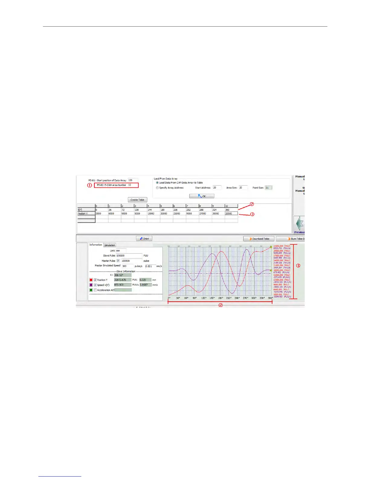
2. After setting up the area number, click on Create Table. Then the software will equally
divide 360 degree equally and put the values into the table according to the area number
set by the user. When E-Cam area number is n, n+ 1 divisions will be shown in the table.
3. Every divided angle that corresponding to a position is put in the table in the unit of PUU.
4. The right down corner of the window will display a complete E-Cam curve. X-axis shows
the angle of E-Cam, from 0° to 360°. Regarding Y-axis, users may select whether to
show position (PUU), speed (PUU/s), or acceleration of the slave axis.
5. When manually creating an E-Cam table, change of position setting should be
reasonable; otherwise, motor overload may occur due to the abrupt speed change or
overcurrent.
Figure 2.22 Manually Create a Table
Speed Fitting Creation
If operating speed becomes users’ first priority when using E-Cam, using Speed Fitting
Creation to create E-Cam curve is recommended.
Figure 2.23 shows the settings of Speed Fitting Creation:
1. Arrange areas according to their proportion in one cycle of E-Cam curve, which includes
waiting area, acceleration area, deceleration area, and stop area.
2. Destination (L) is the total distance the slave axis travels. Its unit is PUU.
3. S-Curve No. is for specifying the smooth level when the position curve transits. The
higher the number the value is, the smoother of motor operation will be during
acceleration and deceleration. Point number of Stop Area is suggested to be set to the
same number as the S-Curve No.

 Loading...


