Introduction of E-Cam Operation ASDA Series Application Note
2-22 March, 2015
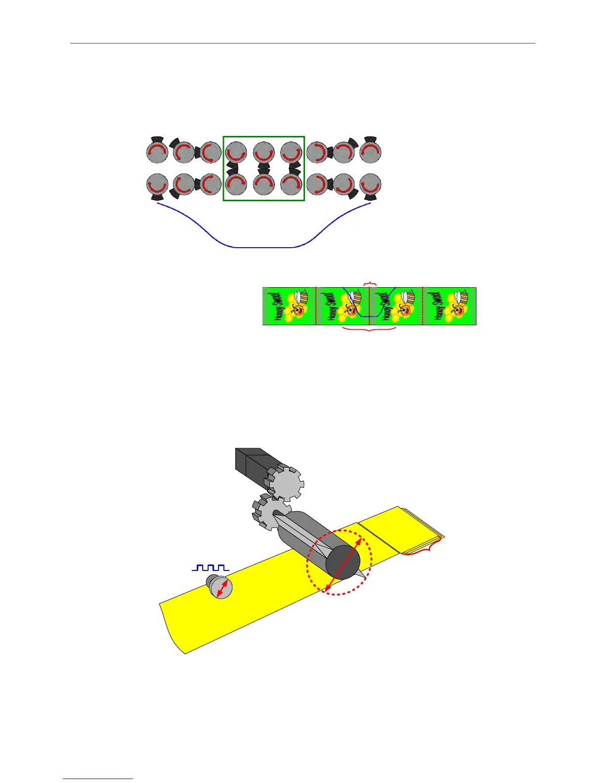
The definition of constant speed area is determined by the proportion of required constant speed
during material feeding, not the constant speed area generated when cutter is operating.
Different material requires different constant speed area. Thus, to generate different E-Cam
curve is required. That is, the constant speed area is determined by the material.
?
º
Constant
Speed Area
360
o
Constant Speed Area
(One Cycle of Curve)
Figure 2.30 Definition of Constant Speed Area
When using software to create an E-Cam curve, the first step is to know the specifications of the
mechanism. Figure 2.31 shows the specifications that users need to know before creating the
curve.
Gear Box
Tooth #A
(to motor)
Tooth #B
(to cutter)
Cutting
Length L
Diameter
d1
Diameter
d2
Encoder pulse
number per
revolution
The
number
of cutter
Figure 2.31 The Mechanism of a Rotary Shear
No matter it is Rotary Shear-W/O Sealing Zone, Rotary Shear- W/T Sealing Zone, or Rotary
Shear- Adjustable Sealing Zone, mechanical specifications is required when creating a curve
via the software. See Figure 2.32.
 Loading...


