ASDA Series Application Note Introduction of E-Cam Operation
March, 2015
2-31
are R>1.)
Take the initial parameter in software as the example:
L (Circumference of printing cylinder) = π x 100 = 314.15 mm
(Pitch of materials) = PL + BL = 200+20=220 mm
R = L / = 314.15 / 220 = 1.428 (R>1, reasonable range)
In addition, L (Circumference of printing cylinder) has to be larger than (Pitch of materials).
The purpose of intermittent motion is to save the use of space and reduce the cost without
idling and wasting the materials.
See Figure 2.44. Users only have to fill in the value according to the setting mechanical
parameters. Please note that the setting of pulse number of encoder and diameter of the
printing axis (d2) should be appropriate. Printing axis is the master axis of printing machine.
Pulse number from the encoder represents the one sent by printing roller per cycle. If master
axis connects to the printing roller, its setting value is (P1-46)*4. If the printing roller is
equipped with decelerator, then the factor needs to be taken into consideration. For instance,
if the decelerator is 1:5, then the setting value should be (P1-46)*4*5.
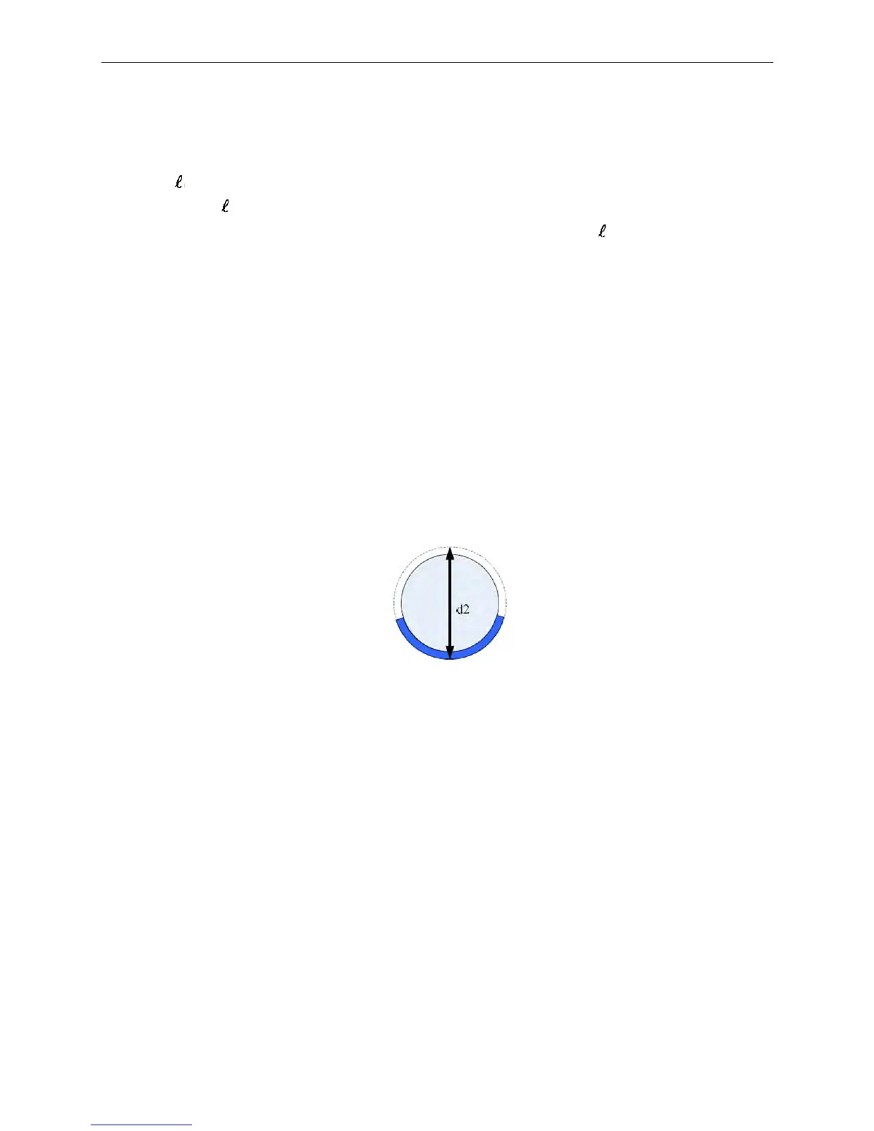
d2: Diameter of printing cylinder includes the length of printing plate. See Figure 2.45.
Figure 2.45 Definition of Printing Cylinder Diameter (d2)
Next, description about how to determine the width of synchronous area is shown is as follows.
See Figure 2.46.
deg_sync (Degree of synchronous area) = PL / L x 360°. This formula can help to calculate the
degree of synchronous area.
Take the initial parameter in software as the example:
deg_sync (Degree of synchronous area) = PL / L x 360° = 200 / 314.15 × 360 = 229.190°
Please note that the setting of degree of waiting area and S-curve cannot exceed 360°.

 Loading...


