ASDA Series Application Note Introduction of E-Cam Operation
March, 2015 2-33
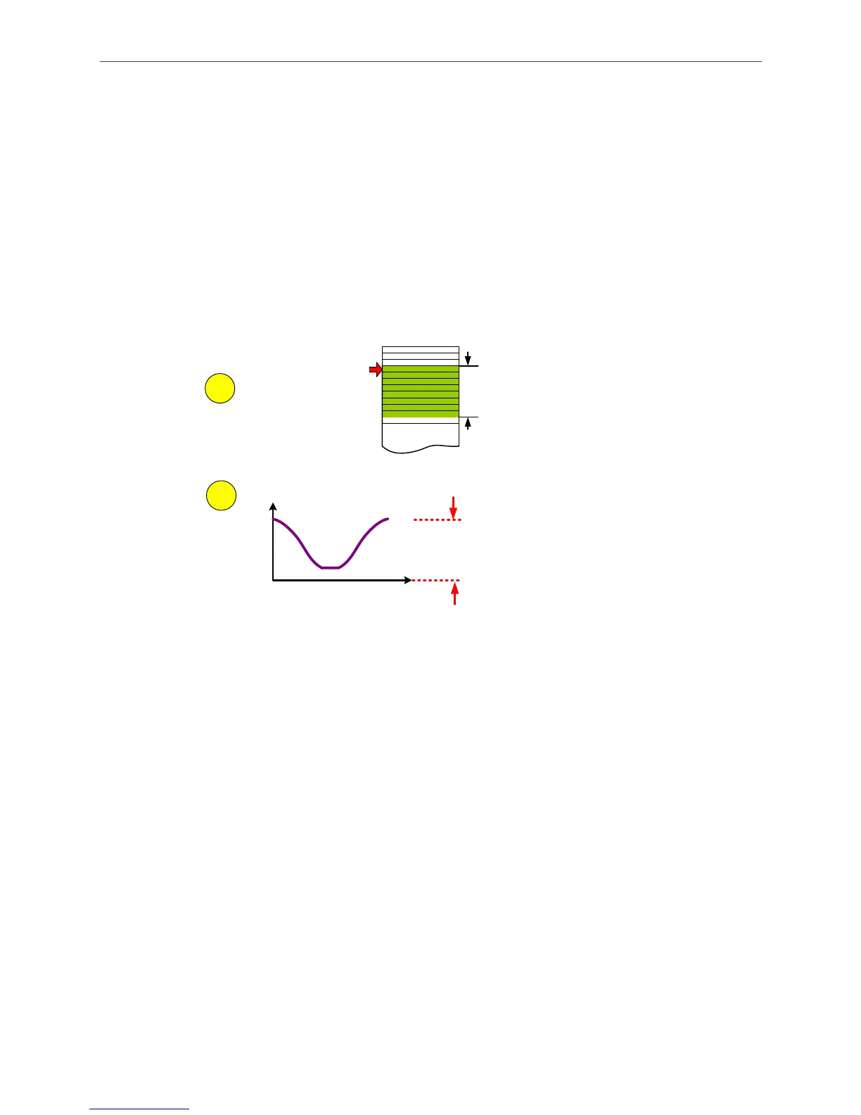
Step 1: When using Macro 6, the first step is to store the required relevant parameters in
data array, which includes P5-81 (the start address of E-Cam curve in data array) and P5-85
(engaging time). When using Macro 6, P5-82 is always set to 7, which means the E-Cam
curve has 7+1 divisions only and cannot be changed.
Step 2: Specify the scaling of the E-Cam curve, which includes the E-gear ratio P1-44/P1-45
(E-Cam is part of the system, which will be influenced by E-gear ratio.) and scaling of E-Cam
curve P5-19.
P5-82 =7 (7+1 items)
(This number is always 7
when using this macro.)
P5-81
The starting
address
P5-85 = 0
Data Array
1
2
Position (PUU)
Slave
Master (Pulse)
Slave E-Gear:
The scaling of E-Cam
curve when output.
P1-44, P1-45, P5-19
Figure 2.48 Relevant Parameter Settings of E-Cam Curve when Using Macro 6
Step 3: See Figure 2.49. Figure out the mechanical specifications and enter relevant
parameters, which is the same as the data required when creating E-Cam curve for rotary
shears. Users may use HMI to input the required data and use HMI or PLC to calculate
relevant values and download them to the servo drive.

 Loading...


