3 Basic Instructions
DVP-PLC Application Manual
3-8
When the SET instruction is driven, its designated device will be “On” and keep being On both when SET instruction
is still being driven or not driven. Use RST instruction to set “Off” the device.
Program Example:
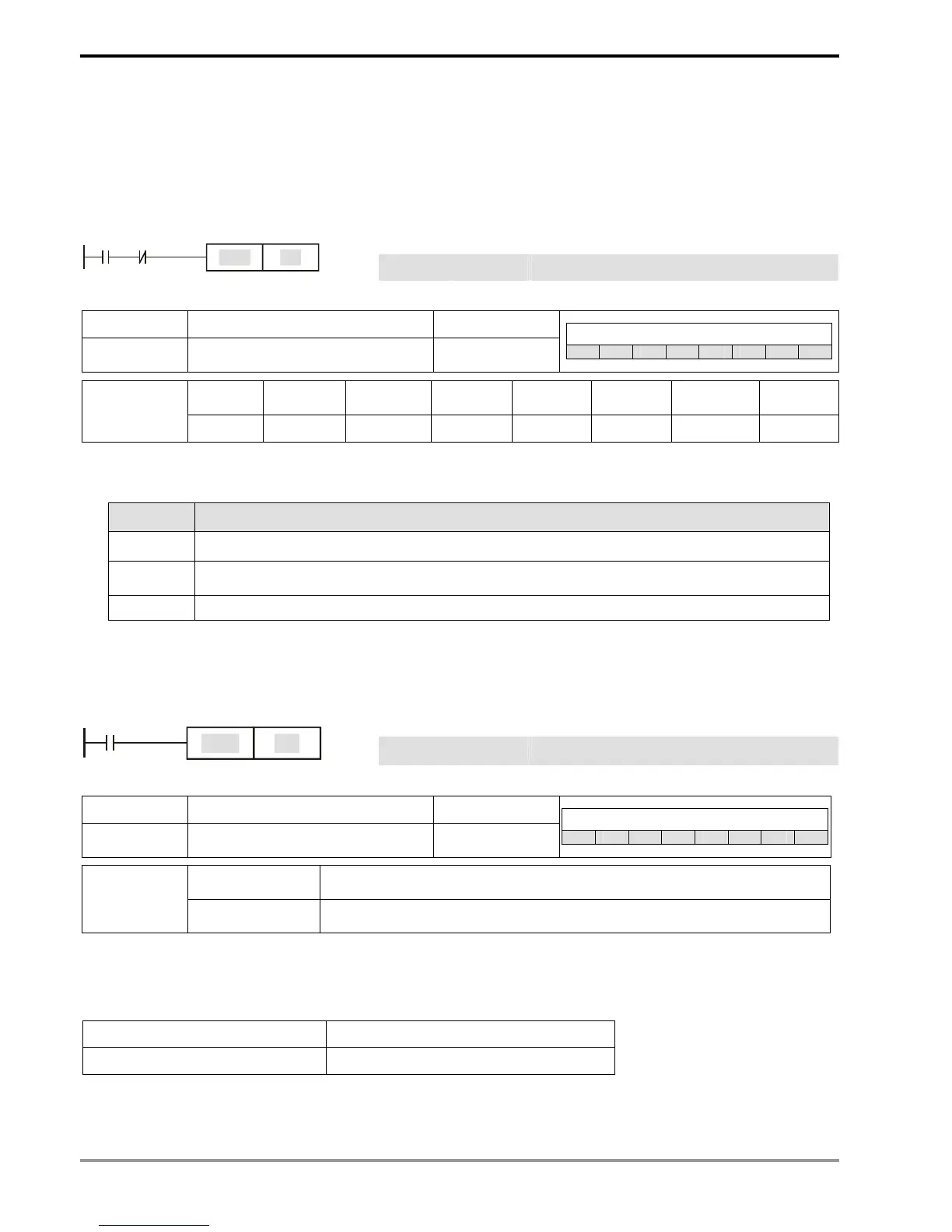
Ladder diagram: Instruction code: Operation:
LD X0 Loading in contact A of X0
ANI Y0 Connecting to contact B of Y0 in series
X0 Y0
Y1
SET
SET Y1
Y1 latched (On)
Mnemonic Function Program steps
RST
Clear the contacts or the registers 1
Controllers
ES EX SS SA SX SC EH SV
X0 ~ X377 Y0 ~ Y377 M0 ~ M4095 S0 ~ S1023 T0 ~ T255 C0 ~ C255 D0 ~ D9999
E0 ~ E7
F0 ~ F7
Operand
-
9 9 9
9
9 9 9
Explanations:
1. When the RST instruction is driven, the actions of the designated devices are:
Device Status
Y, M, S, Coil and contact will be set to “Off”
T, C
Present values of the timer or counter will be set to “0”, and the coil and contact will be set to
“Off”
D, E, F The content will be set to “0”.
2. If RST instruction is not being executed, the status of the designated device will stay intact.
Program Example:
Ladder diagram: Instruction code: Operation:
LD X0 Loading in contact A of X0
X0
Y5
RST
RST Y5 Resetting contact Y5
Mnemonic Function Program steps
TMR
16-bit timer 1
Controllers
ES EX SS SA SX SC EH SV
T-K T0 ~ T255, K0 ~ K32,767
Operand
T-D T0 ~ T255, D0 ~ D9999
Explanations:
When TMR instruction is executed, the designated coil of the timer will be On and the timer will start to time. When the
set value in the timer is reached (present ≥ set value), the contact will be:
NO (Normally Open) contact Open collector
NC (Normally Closed) contact Close collector