3 Basic Instructions
DVP-PLC Application Manual
3-9
Program Example:
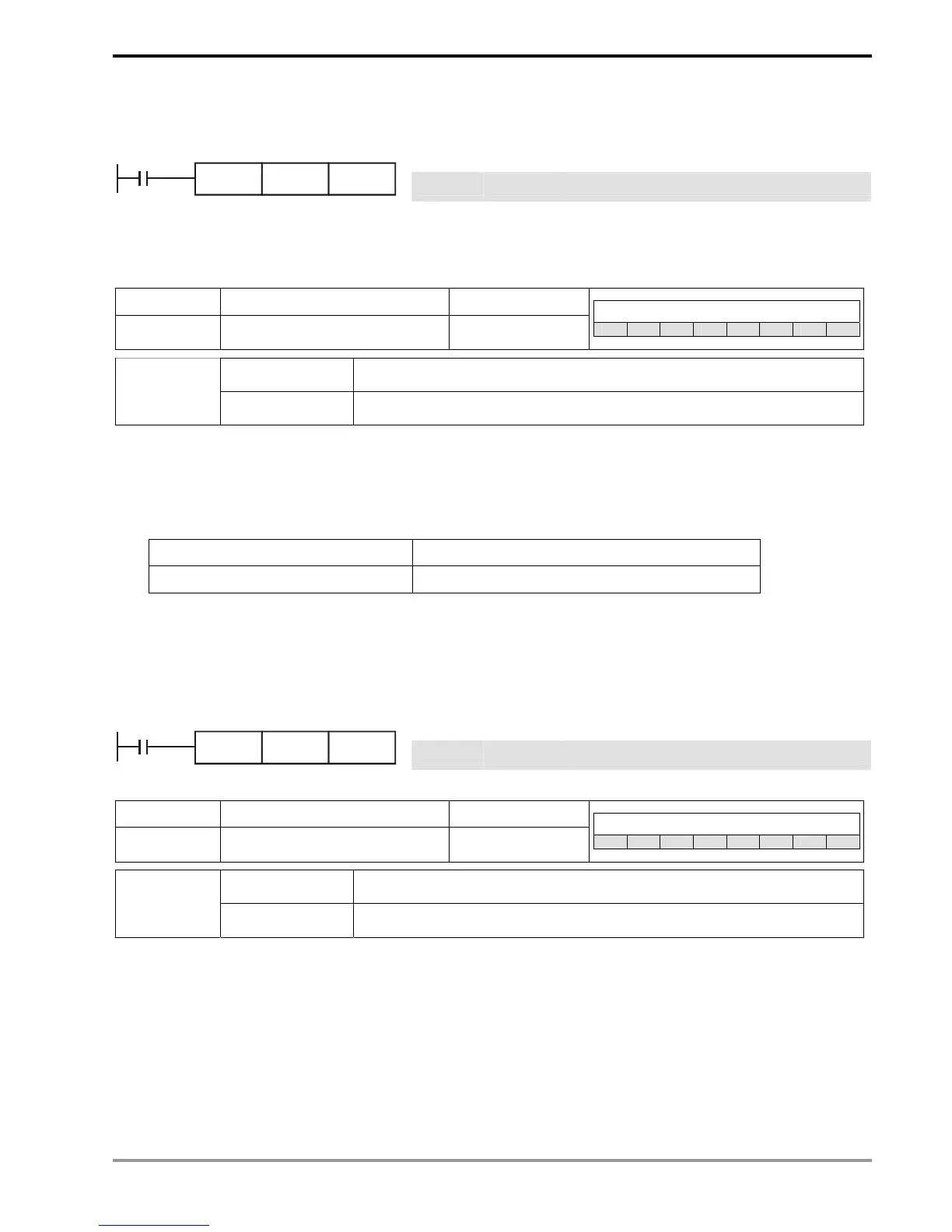
Ladder diagram: Instruction code: Operation:
LD X0 Loading in contact A of X0 T5 timer
X0
T5TMR
K1000
TMR T5 K1000 Set value in timer T5 as K1,000
Remarks:
See the specification of each model for the range of operand T.
Mnemonic Function Program steps
CNT
16-bit counter 1
Controllers
ES EX SS SA SX SC EH SV
C-K C0 ~ C199, K0~K32,767
Operand
C-D C0 ~ C199, D0 ~ D9999
Explanations:
1. When the CNT instruction goes from Off to On, the designated counter coil will be driven, and the present value
in the counter will plus 1. When the counting reaches the set value (present value = set value), the contact will
be:
NO (Normally Open) contact Open collector
NC (Normally Closed) contact Close collector
2. If there are other counting pulse input after the counting reaches its target, the contact and present value will
stay intact. Use RST instruction to restart or reset the counting.
Program Example:
Ladder diagram: Instruction code: Operation:
LD X0 Loading in contact A of X0
X0
C20CNT
K100
CNT C20 K100 Set value in counter C20 as K100
Mnemonic Function Program steps
DCNT
32-bit counter 1
Controllers
ES EX SS SA SX SC EH SV
C-K C200 ~ C255, K-2,147,483,648 ~ K2,147,483,647
Operand
C-D C200 ~ C255, D0 ~ D9999
Explanations:
1. DCNT is the instruction for enabling the 32-bit high-speed counters C200 ~ C255.
2. For general purpose addition/subtraction counters C200 ~ C234, when DCNT goes from Off to On, the present
value in the counter will pulse 1 (counting up) or minus 1 (counting down) according to the modes set in special
M1200 ~ M1235.
3. For high-speed addition/subtraction counters C235 ~ C255, when the high-speed counting pulse input goes
from Off to On, the counting will start its execution. For the input terminals (X0 ~ X17) and counting methods