7 Application Instructions API 50-99
DVP-PLC APPLICATION MANUAL
7-27
7. EH series MPU has two groups of A-B phase pulse output from CH0 (Y0, Y1) and CH1 (Y2, Y3); EH2/SV series
MPU has four groups of A-B phase pulse output from CH0 (Y0, Y1), CH1 (Y2, Y3), CH2 (Y4, Y5) and CH3 (Y6,
Y7). See 2.3 and remarks for how to set up.
8. When PLSY instruction is executed, it will designate the number of output pulses (S
2
) output from the output
device (D) at a pulse output frequency (S
1
).
9. When PLSY instruction is used in the program, its outputs cannot be the same as those in API 58 PWM and API
59 PLSR.
10. Pulse output completed flags for all series:
MPU
ES/EX/SS
SA/SX/SC
SC EH/EH2/SV EH2/SV
Output device Y0 Y1 Y10 Y11 Y0 Y2 Y4 Y6
Flag M1029 M1030 M1102 M1103 M1029 M1030 M1036 M1037
11. For ES/EX/SS/SA/SX/SC/EH series MPU, when PLSY and DPLSY instruction is disabled, the pulse output
completed flags will all be Off automatically.
12. For EH2/SV series MPU, when PLSY and DPLSY instruction is disabled, the user will have to reset the pulse
output completed flags.
13. The user has to reset the pulse output completed flags after the pulse output is completed.
14. After PLSY instruction starts to be executed, Y will start a pulse output. Modifying S
2
at this moment will not
affect the current output. If you wish to modify the number of output pulses, you have to first stop the execution
of PLSY instruction and modify the number.
15. S
1
can be modified when the program executes to PLSY instruction.
16. Off time : On time of the pulse output = 1 : 1.
17. When the program executes to PLSY instruction, the current number of output pulses will be stored in the
special data registers D1336 ~ D1339. See remarks for more details.
18. For SA/EH series MPU, there is no limitation on the times using this instruction. For SA/SX/SC/EH series MPU,
the program allows two instructions being executed at the same time. For EH2/SV series MPU, the program
allows four instructions being executed at the same time.
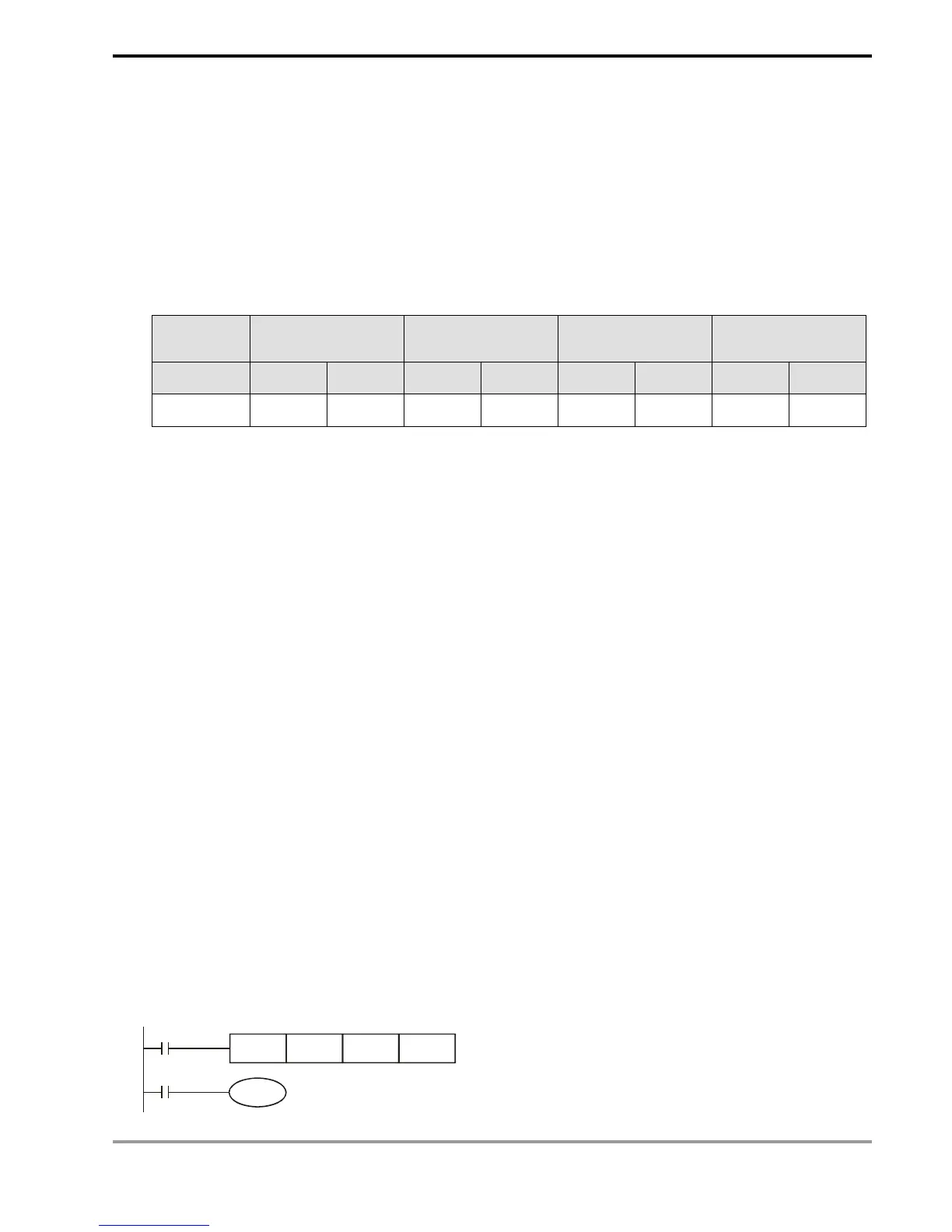
Program Example:
1. When X0 = On, there will be 200 pulses output from Y0 at 1KHz. When the pulse output is completed, M1029
will be On and Y10 will be On.
2. When X0 = Off, the pulse output from Y0 will stop immediately. When X0 is On again, the output will start again
ffrom the first pulse.
X0
PLSY K1000 K200 Y0
M1029
Y10