7 Application Instructions API 50-99
DVP-PLC APPLICATION MANUAL
7-81
Off (DO NOT use the program to execute RST M1122). After 1ms of waiting, PLC will start to receive the 10 data.
Store the data in consecutive registers starting from D120.
3. When the receiving of data is completed, M1123 will automatically be On. After the program finishes processing
the received data, M1123 has to be reset to Off and the PLC will start to wait for the sending and receiving of
data again. DO NOT use the program to continuously execute RST M1123.
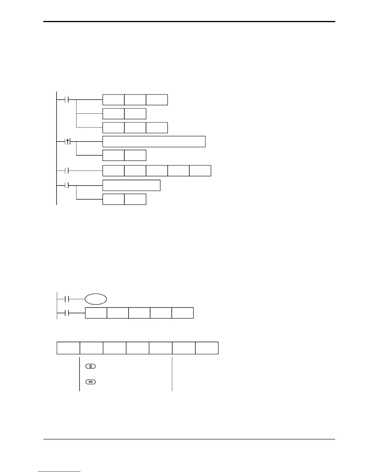
MOV
D1120H86
M1002
SET
M1120
SET M1122
MOV D1129K100
X10
M1123
RST
M1123
RS D100 K10 D120 K10
Process of received data
Set up communication protocol 9600,7,E,1
Retain communication protocol
Set up communication time-out 100ms
Set up sending request
Receiving of data is completed the flag is reset.
Write in the data to be transmitted in advance
Sending request
pulses
Receiving
completed
The flag is reset.
Program Example 2:
Switching between 8-bit mode (M1161 = On) and 16-bit mode (M1161 = Off)
1. 8-bit mode:
The head code and tail code of the data are set up by M1126 and M1130 together with D1124 ~ D1126. When
PLC is executing RS instruction, the head code and tail code set up by the user will be sent out automatically.
M1161 = On indicates PLC in 8-bit conversion mode. The 16-bit data will be divided into the higher 8 bits and
lower 8 bits. The higher 8 bits are ignored and only the lower 8 bits are valid for data transmission.
M1000
M1161
D100 D120
K4 K7RS
X0
Sending data: (PLC -> external equipment)
STX
D100L D101L D102L D103L
ETX1 ETX2
Head
code
source data register, starting from
the lower 8 bits of D100
length = 4
Tail co d e
1
Tail code
2
Receiving data: (External equipment -> PLC)