7 Application Instructions API 50-99
DVP-PLC APPLICATION MANUAL
7-82
D120L D122L D123L D124L D125L D126LD121L
Head
code
Tail code
1
Tail code
2
received data register, starting from
the lower 8 bits of D120
length = 7
When receiving data, PLC will receive the head code and tail code of the data from the external equipment;
therefore, the user has to be aware of the setting of data length n.
2. 16-bit mode:
The head code and tail code of the data are set up by M1126 and M1130 together with D1124 ~ D1126. When
PLC is executing RS instruction, the head code and tail code set up by the user will be sent out automatically.
M1161 = Off indicates PLC in 16-bit conversion mode. The 16-bit data will be divided into the higher 8 bits and
lower 8 bits for data transmission.
M1001
M1161
D100 D120
K4
K7
RS
X0
Sending data: (PLC -> external equipment)
STX
D100L D100L D101L D101L
ETX1 ETX2
Head
code
source data register, starting from
the lower 8 bits of D100
length = 4
Tail code
1
Tail code
2
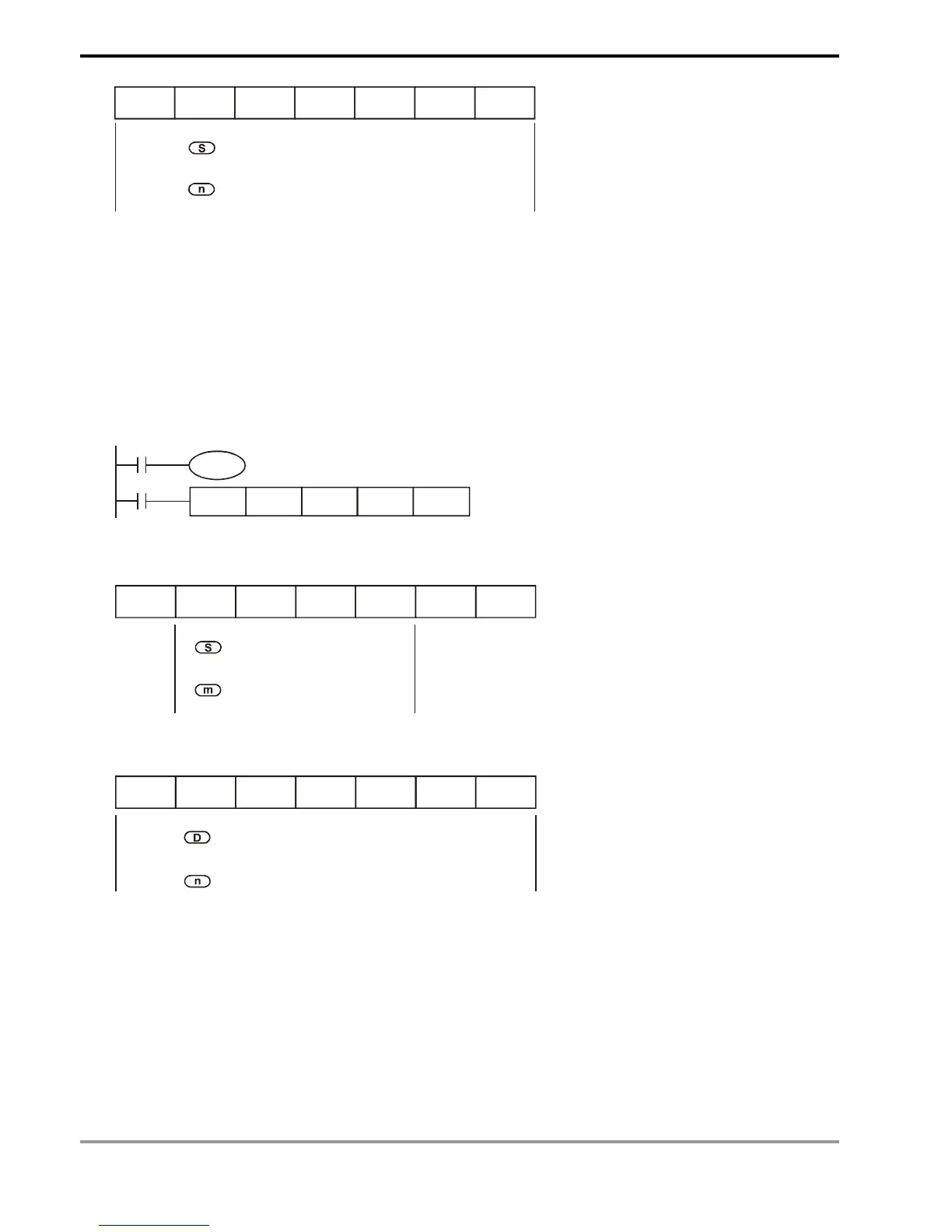
Receiving data: (External equipment -> PLC)
D120L D120H D121L D121H D122L D122H D123L
Tail code
1
Tail code
2
received data register, starting from
the lower 8 bits of D120
length = 7
Head
code
When receiving data, PLC will receive the head code and tail code of the data from the external equipment;
therefore, the user has to be aware of the setting of data length n.
Program Example 3:
Connect PLC to VFD-B series AC motor drives (AC motor drive in ASCII Mode; PLC in 16-bit mode and M1161 = Off).
Write in the 6 data starting from parameter address H2101 in VFD-B in advance as the data to be transmitted.