8 Application Instructions API 100-149
DVP-PLC Application Manual
8-20
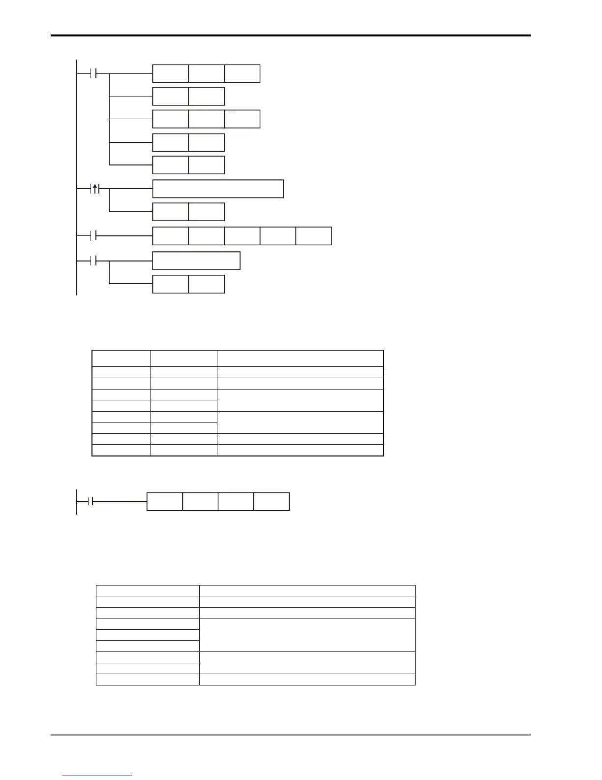
M1002
X10
M1123
RST M1123
RS D100 K8 D120 K8
SET M1143
SET M1161
RTU Mode
8-bit Mode
Write transmitting data in advance
transmission
request
pulse
Receiving completed and flag reset
MOV D1120H87
SET M1120
MOV D1129K100
Set up communication protocol
to 9600, 8, E, 1
Retain communication protocol
Set up communication
time-out: 100ms
SET M1122
Set up transmission request
receiving completed
Process received data
PLC VFD-S, PLC sends: 01 06 2000 0012 02 07
Registers for sent data (sending messages)
Register DATA Explanation
D100 low 01 H Address
D101 low 06 H Function
D102 low 20 H
D103 low 00 H
Data address
D104 low 00 H
D105 low 12 H
Data content
D106 low 02 H CRC CHK 0
D107 low 07 H CRC CHK 1
The error checksum CRC CHK (0,1) can be calculated by CRC instruction (in 8-bit mode, M1161 = On).
M1000
CRC D100 K6 D106
CRC checksum: 02 H is stored in the lower 8 bits of D106 and 07 H in the lower 8 bits of D107,
Remarks:
1. The format of RTU mode with a communication datum
START Time interval
Address Communication address: 8-bit binary
Function Function code: 8-bit binary
DATA (n-1)
…….
DATA 0
Data content:
n × 8-bit data
CRC CHK Low
CRC CHK High
CRC checksum:
16-bit CRC checksum consists of 2 8-bit binaries
END Time interval
2. CRC checksum starts from Address and ends at Data content.