9 Application Instructions API 150-199
DVP-PLC Application Manual
9-8
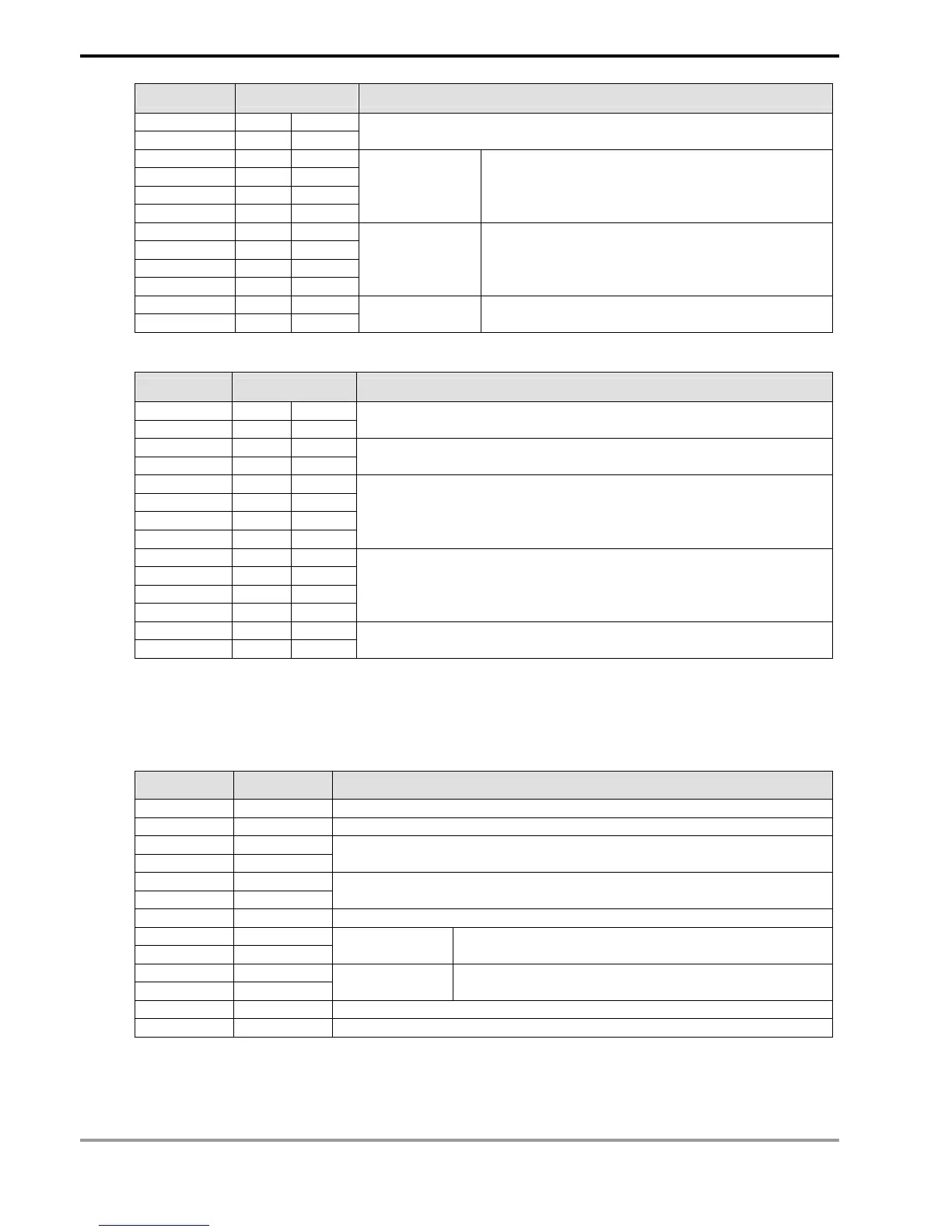
Register DATA Explanation
D1262 Low ‘0’ 30 H
D1262 High ‘4’ 34 H
Byte Count
D1263 Low ‘0’ 30 H
D1263 High ‘0’ 30 H
D1264 Low ‘1’ 31 H
D1264 High ‘2’ 32 H
Data contents 1 The content of register D50 (H12)
D1265 Low ‘1’ 31 H
D1265 High ‘7’ 37 H
D1266 Low ‘7’ 37 H
D1266 High ‘0’ 30 H
Data contents 2 The content of register D51 (H1770 = K6,000)
D1267 Low ‘3’ 33 H LRC CHK 1
D1267 High ‘0’ 30 H LRC CHK 0
Error checksum: LRC CHK (0,1)
Registers for received data (responding messages)
Register DATA Explanation
D1070 Low ‘0’ 30 H ADR 1
D1070 High ‘1’ 31 H ADR 0
D1071 Low ‘1’ 31 H CMD 1
D1071 High ‘0’ 30 H CMD 0
D1072 Low ‘2’ 32 H
D1072 High ‘0’ 30 H
D1073 Low ‘0’ 30 H
D1073 High ‘0’ 30 H
Data Address
D1074 Low ‘0’ 30 H
D1074 High ‘0’ 30 H
D1075 Low ‘0’ 30 H
D1075 High ‘2’ 32 H
Number of Registers
D1076 Low ‘C’ 43 H LRC CHK 1
D1076 High ‘D’ 44 H LRC CHK 0
9. RTU Mode: When PLC is connected to VFD-S AC motor drives
PLC Ö VFD-S, PLC sends: “01 10 2000 0002 04 0012 1770 C4 7F”
VFD-S Ö PLC, PLC receives: “01 10 2000 0002 4A 08”
Registers for send data (sending messages)
Register DATA Explanation
D1256 Low 01 H Address
D1257 Low 10 H Function
D1258 Low 20 H
D1259 Low 00 H
Data Address
D1260 Low 00 H
D1261 Low 02 H
Number of Registers
D1262 Low 04 H Byte Count
D1263 Low 00 H
D1264 Low 12 H
Data content 1 The content of register D50 (H12)
D1265 Low 17 H
D1266 Low 70 H
Data content 2 The content of register D51 (H1770 = K6,000)
D1267 Low C4 H CRC CHK Low
D1268 Low 7F H CRC CHK High