9 Application Instructions API 150-199
DVP-PLC Application Manual
9-9
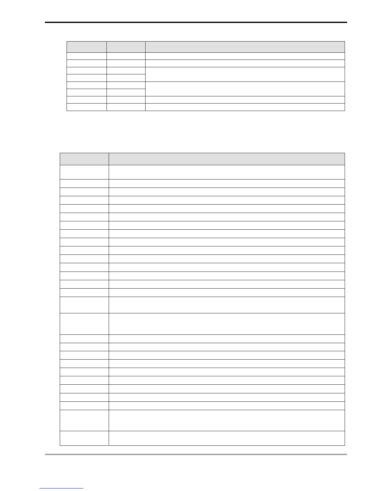
Registers for received data (responding messages)
Register DATA Explanation
D1070 Low 01 H Address
D1071 Low 10 H Function
D1072 Low 20 H
D1073 Low 00 H
Data Address
D1074 Low 00 H
D1075 Low 02 H
Number of Registers
D1076 Low 4A H CRC CHK Low
D1077 Low 08 H CRC CHK High
Remarks:
1. The activation condition placed before MODRD, RDST and MODRW instructions cannot use rising-edge or
falling-edge contacts; otherwise the data stored in the registers for received data will encounter errors.
2. Flags and special registers for MODRW instruction in RS-485 communication. (For details, see API 80 RS).
Flags Function
M1120
For retaining communication setups. After the setup is made, changes in D1120 will be
invalid.
M1121 When Off, RS-485 is sending data.
M1122 Sending request
M1123 Receiving is completed
M1124 Waiting for receiving data
M1125 Disable receiving status
M1126 Selecting STX/ETX system
M1127 Sending/receiving data through MODRD / RDST / MODRW instructions is completed.
M1128 Sending data…/receiving data…
M1129 Receiving data time-out
M1130 User/system defined STX/ETX
M1131 On when MODRD / MODWR / MODRW is converting data to hex
M1140 MODRD / MODWR / MODRW data receiving error
M1141 MODRD / MODWR / MODRW parameter error
M1142 VFD-A handy instruction data receiving error
M1143
ASCII/RTU mode selection (used with MODRD/MODWR/MODRW) (Off = ASCII mode;
On = RTU mode)
D1070 ~ D1085
When the built-in RS-485 communication instruction is executed and sends out data, the
receiving end will respond with a message and the message will be stored in D1070 ~
D1085. The user can check the registers for the messages.
D1120 RS-485 communication protocol
D1121 PLC communication address (saving PLC communication address; latched)
D1122 Remaining words of the sent data
D1123 Remaining words of the received data
D1124 Start text definition (STX)
D1125 Definition of end text 1 (ETX1)
D1126 Definition of end text 2 (ETX2)
D1129 Abnormal communication time-out. Unit: ms
D1130 Records of error codes sent back from MODBUS
D1256 ~ D1295
When the built-in RS-485 communication instruction MODRW is executed, the sent out
data will be stored in D1256 ~ D1295. The user can check whether the instruction is
correct by the contents in the registers.
D1296 ~ D1311
PLC will automatically convert the ASCII data stored in the register designated by the user
into hex format.