9 Application Instructions API 150-199
DVP-PLC Application Manual
9-35
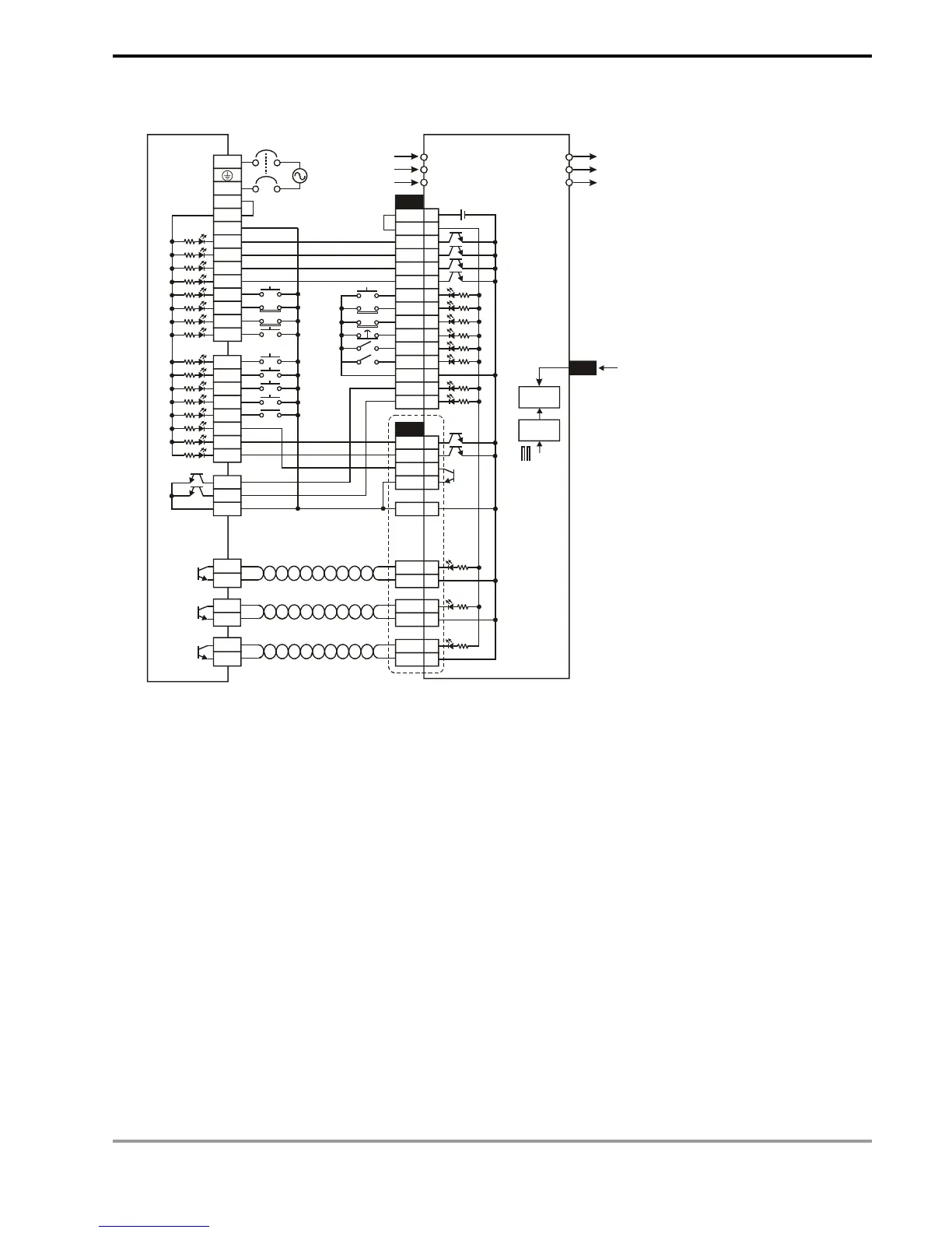
6. Wiring of DVP-EH series PLC and a Mitsubishi MR-J2-□A Servo drive:
L
N
X0
X1
X2
X3
X4
X5
X6
S/S
+24V
200KPPS
R
S
T
U
V
W
24V
24G
X7
X10
X11
X12
X13
X14
X15
X16
X17
Y6
Y7
C4
Y4
Y0
Y1
C2
C0
C1
DOG
JOG(+)
JOG(-)
CN1B
VDD
COM
D01
ZSP
TLC
ALM
RES
LSP
LSN
EMG
TL
SON
SG
Clear pulse
Pulse output
Forward/backward direction
Note:
(a) When detecting an absolute position by using DABSR instruction, the parameter setting of a Mitsubishi
MR-J2-□A servo drive that connects to Delta EH series PLC:
P0: position mode.
P1: using absolute value.
P21: pulse input type as Pulse+DIR.
(b) The forward/reverse limit switch should be connected to SERVO AMP.
(c) When using OP (Z-phase signal) in servo and given that the Z-phase signal is a high-frequency one when
the motor is running at high speed, the valid detection can only be possible when the signal is within the
range detectable by PLC. When using OP (Z phase signal) of the servo, if Z phase signal is a high
frequency signal during high-speed motor operation, the high frequency signal shall be within the available
range that can be detected by PLC.
7. Cautions when designing a position control program:
a) There is no limitation on the times of using the position control instructions, API 156 ZRN, API 157 PLSV,
API 158 DRVI, and API 159 DRVA. However, the user still have to note that: