2 Functions of Devices in DVP-PLC
DVP-PLC Application Manual
2-59
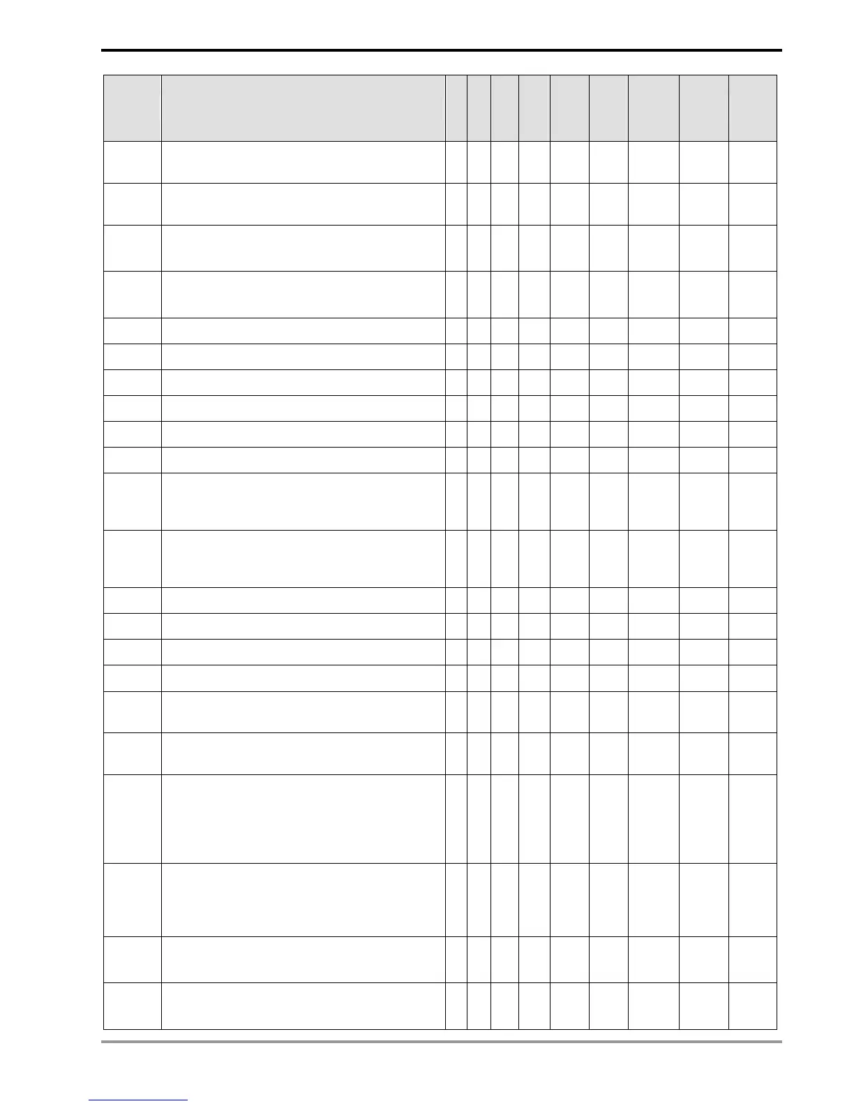
Special D Function
ES
EX
SS
SA
SX
SC
EH
EH2
SV
Off
Ø
On
STOP
Ø
RUN
RUN
Ø
STOP
Attribute Latched Default
D1212*
Start latched address for 32-bit high-speed counters
C235 ~ C255
╳
○ ○
- - - R/W YES 235
D1213*
End latched address for 32-bit high-speed counters
C235 ~ C255
╳
○ ○
- - - R/W YES 255
D1214*
Start latched address for steps S0 ~ S899
# -> EH: 500; SA/SX/SC: 512
╳
○ ○
- - - R/W YES #
D1215*
End latched address for steps S0 ~ S899
# -> EH: 899; SA/SX/SC: 895
╳
○ ○
- - - R/W YES #
D1216* Start latched address for registers D0 ~ D999
╳
○ ○
- - - R/W YES 200
D1217* End latched address for registers D0 ~ D999
╳
○ ○
- - - R/W YES 999
D1218* Start latched address for registers D2000 ~ D9999
╳
○ ○
- - - R/W YES 2,000
D1219* End latched address for registers D2000 ~ D9999
╳
○ ○
- - - R/W YES #
D1220 Phase of the 1
st
group pulse output CH0 (Y0, Y1)
╳ ╳
○
0 - - R/W NO 0
D1221 Phase of the 2
nd
group pulse output CH1 (Y2, Y3)
╳ ╳
○
0 - - R/W NO 0
D1222
Time difference between direction signal and pulse
output for the 1
st
group pulse CH0 (Y0, Y1) in DRVI,
DDRVI, DRVA, DDRVA, PLSV, DPLSV
╳ ╳
○
0 - - R/W NO 0
D1223
Time difference between direction signal and pulse
output for the 2
nd
group pulse CH1 (Y2, Y3) in DRVI,
DDRVI, DRVA, DDRVA, PLSV, DPLSV
╳ ╳
○
0 - - R/W NO 0
D1225 Counting mode of the counter HHSC0
╳ ╳
○
2 - - R/W NO 2
D1226 Counting mode of the counter HHSC1
╳ ╳
○
2 - - R/W NO 2
D1227 Counting mode of the counter HHSC2
╳ ╳
○
2 - - R/W NO 2
D1228 Counting mode of the counter HHSC3
╳ ╳
○
2 - - R/W NO 2
D1129
Phase of the 3
rd
group pulse output CH2 (Y4, Y5)
(available in EH2/SV)
╳ ╳
○
0 - - R/W NO 0
D1130
Phase of the 4
th
group pulse output CH3 (Y6, Y7)
(available in EH2/SV)
╳ ╳
○
0 - - R/W NO 0
D1256
↓
D1295
When the RS-485 communication instruction
MODRW built-in the PLC is executed, the words of
sent out by the instruction will be stored in D1256 ~
D1259. You can check whether the instruction is
correct by the contents in these registers.
○ ○ ○
0 - - R NO 0
D1296
↓
D1311
The RS-485 communication instruction MODRW
built in the PLC automatically converts the ASCII
data received in the designated register into hex and
store the hex data into D1296 ~ D1311.
○ ○ ○
0 - - R NO 0
D1313*
Second in RTC: 00 ~ 59
#: read RTC and write
╳
○ ○
# - - R/W NO 0
D1314*
Minute in RTC: 00 ~ 59
#: read RTC and write
╳
○ ○
#
- - R/W NO 0