3 Functions of Devices in DVP-PM
DVP-PM Application Manual
3-70
automatically be defined, and PG1 signal which stops the positioning immediately is only valid when it is out
of the mask area. When PG1 is triggered, the clear signal CLR1 will be triggered automatically after 20μs. In
addition, the positioning speed is operated according to V(I), and
the pulses are sent out by the pulse
generator.
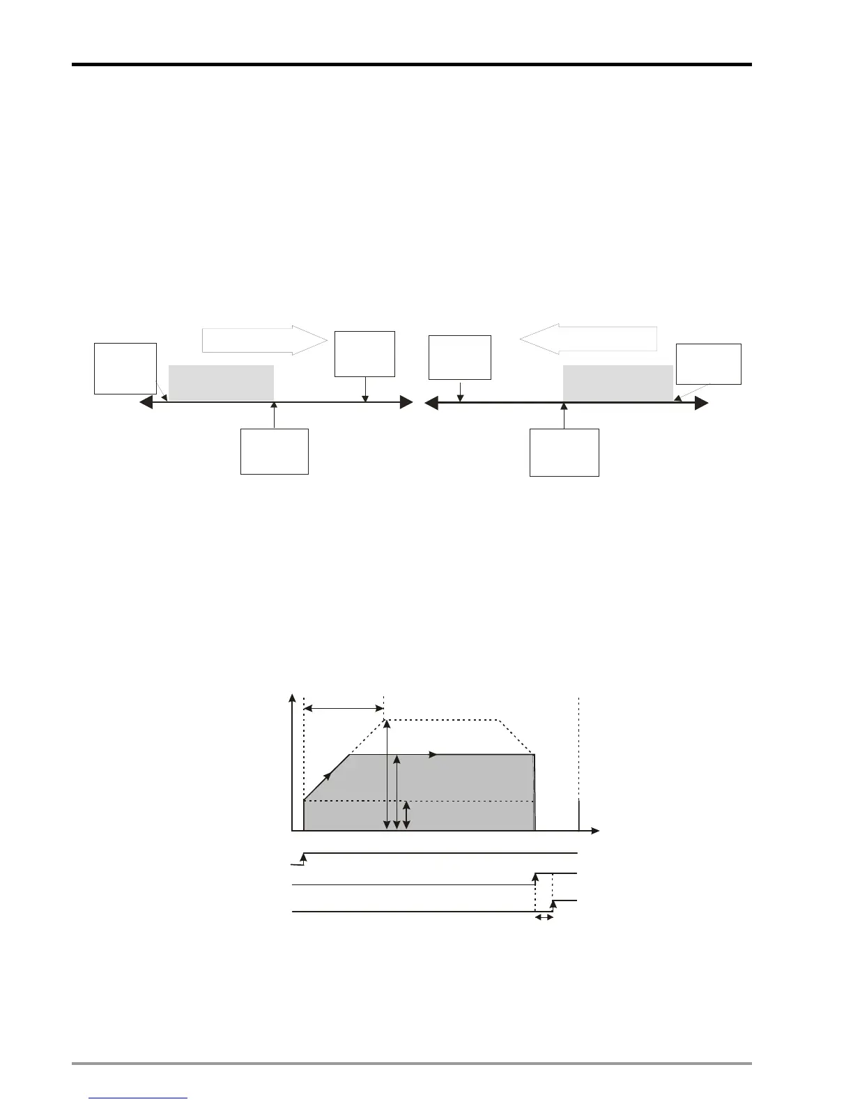
♦ The mask area is defined by current position and the target position as below diagrams. If the current
position is smaller than the target position, the positioning will be operated in forward direction. If the current
positon is bigger than the target position, the positioning will be operated in backward direction. In both
cases, the mask area will be the range between current position and 0.
Forward operation Backward operation
Current
position
(D1928=0)
Mask area
Current
position
(D1928)
Tar g et
position
(D1918)
Operation direction
Current
position
(D1928=0)
Mask area
Operation direction
Current
position
(D1928)
Tar get
position
(D1918)
♦ Operation direction: Direction of relative positioning is determined by the sign bit of the value for P(I) (set in
D1838, D1918, D1998). Direction of absolute positioning is determined by current position (CP). Forward
running occurs when P(I) is bigger than CP. Reverse running occurs when P(I) is smaller than CP.
♦ The operation speed will be stable after the speed is accelerated from V
BIAS
to the expected V(I). When PG1
is triggered out of the mask area, the positioning stops immediately.
♦ The registers involved: D1824 (D1904, D1984) (V
BIAS
), D1840 (D1920, D2000) (V(I)), D1822 (D1902,
D1982) (V
MAX
), D1838 (D1918, D1998) (P(I)) and D1836 (D1916, D1996) (T
ACC
)
Speed
T
ACC
V
MAX
Time
V
BIAS
DOG1
V(I)
PG1
CLR1
20 s
µ
9. b8 of D1846 (D1926, D2006, D2086): enabling single-speed positioning
♦ When b[8] is triggered, i.e. single-speed positioning is enabled, and START = ON, the single-speed
positioning will be started. The pulse generator will send out pulses according to the setting of P(I) and V(I).
♦ Operation direction: Direction of relative positioning is determined by the sign bit of the value for P(I) (set in
D1838, D1918, D1998, D2078). Direction of absolute positioning is determined by current position (CP).
 Loading...


