3 Functions of Devices in DVP-PM
DVP-PM Application Manual
3-69
operation speed achieves stable status, you can modify V(I), and the pulse output from DVP-PM will
accelerate or decelerate according to the modification. In this case, the external STOP input signal cannot
stop the pulse output from DVP-PM. To stop the pulse output, you have to trigger the STOP function (b0 of
D1846 (D1926, D2006).
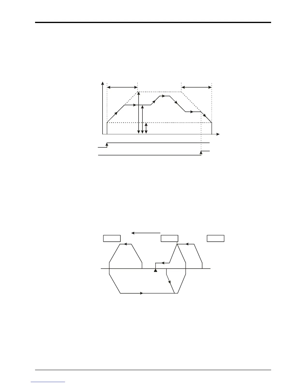
♦ Timing diagram:
Speed
T
ACC
DEC
V
MAX
Time
V
BIAS
Start
Stop
V(I)
6. b5 of D1846 (D1926, D2006, D2086): manual pulse generator (MPG) input
♦ b[5] = 1: enabling MPG input. See D1858 ~ D1864 (D1938 ~ D1944, D2018 ~ D2024) for more details.
7. b6 of D1846 (D1926, D2006): enabling zero return mode
♦ b[6] = 0→1: starting zero return. The motions of zero return vary depending on different current positions
(CP)
Zero return path:
LSN DOG
LSP
[4]
[3]
[2]
[1]
Direction of
zero return
Negative Limit Switch
Positive Limit Switch
Zero
CP [1]: On the right of zero point and DOG sensor; DOG = OFF.
CP [2]: On the right of zero point; DOG = ON.
CP [3]: On the left of zero point and DOG sensor; DOG = OFF, LSN = OFF.
CP [4]: On the left of zero point; DOG = OFF, LSN = ON.
Note: DVP-10PM do not have LSN/LSP signals, therefore the motions on CP[3] and CP[4] are not available.
8. b7 of D1926: Externally triggering single-speed positioning
♦ b[7] = 0→1: Enabling single-speed positioning triggered by external signal(DOG1). When b7 of D1926 is
ON and DOG1 is triggered, single-speed positioning will be executed. In this case, a mask area will
 Loading...


