4 Basic Instructions
DVP-PM Application Manual
4-6
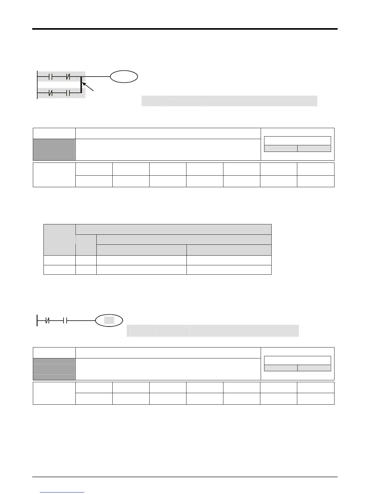
Ladder diagram: Instruction: Operation:
LD X0
Load NO contact X0
ANI X1
Connect NC contact X1 in series
LDI X2
Load NC contact X2
AND X3
Connect NO contact X3 in series
ORB
Connect circuit block in parallel
X0
X2
Y1
X1
X3
ORB
Block A
Block B
OUT Y1
Drive Y1 coil
Mnemonic Function
OUT
Output Coil
Controllers
20PM 10PM
X0~X377 Y0~Y377 M0~M4095 S0~S1023 T0~T255 C0~C255 D0~D9999
Operand
-
9 9 9
- - -
Explanations:
1. Output the program evaluation results before OUT instruction to the designated device.
2. Status of coil contact:
OUT instruction
Associated Contacts
Evaluation
result
Coil
NO contact(normally open) NC contact(normally close)
FALSE OFF Current blocked Current flows
TRUE ON Current flows Current blocked
Program Example:
Ladder diagram: Instruction: Operation:
LDI X0 Load NC contact X0
AND X1 Connect NO contact X1 in series
X0 X1
Y1
OUT Y1
Drive Y1 coil
Mnemonic Function
SET
Latches the ON status
Controllers
20PM 10PM
X0~X377 Y0~Y377 M0~M4095 S0~S1023 T0~T255 C0~C255 D0~D9999
Operand
-
9 9 9
- - -
Explanations:
When the SET instruction is driven, its designated device will be ON and latched whether the SET instruction is still
driven. In this case, RST instruction can be applied to turn off the device.
Program Example:

 Loading...


