4 Basic Instructions
DVP-PM Application Manual
4-7
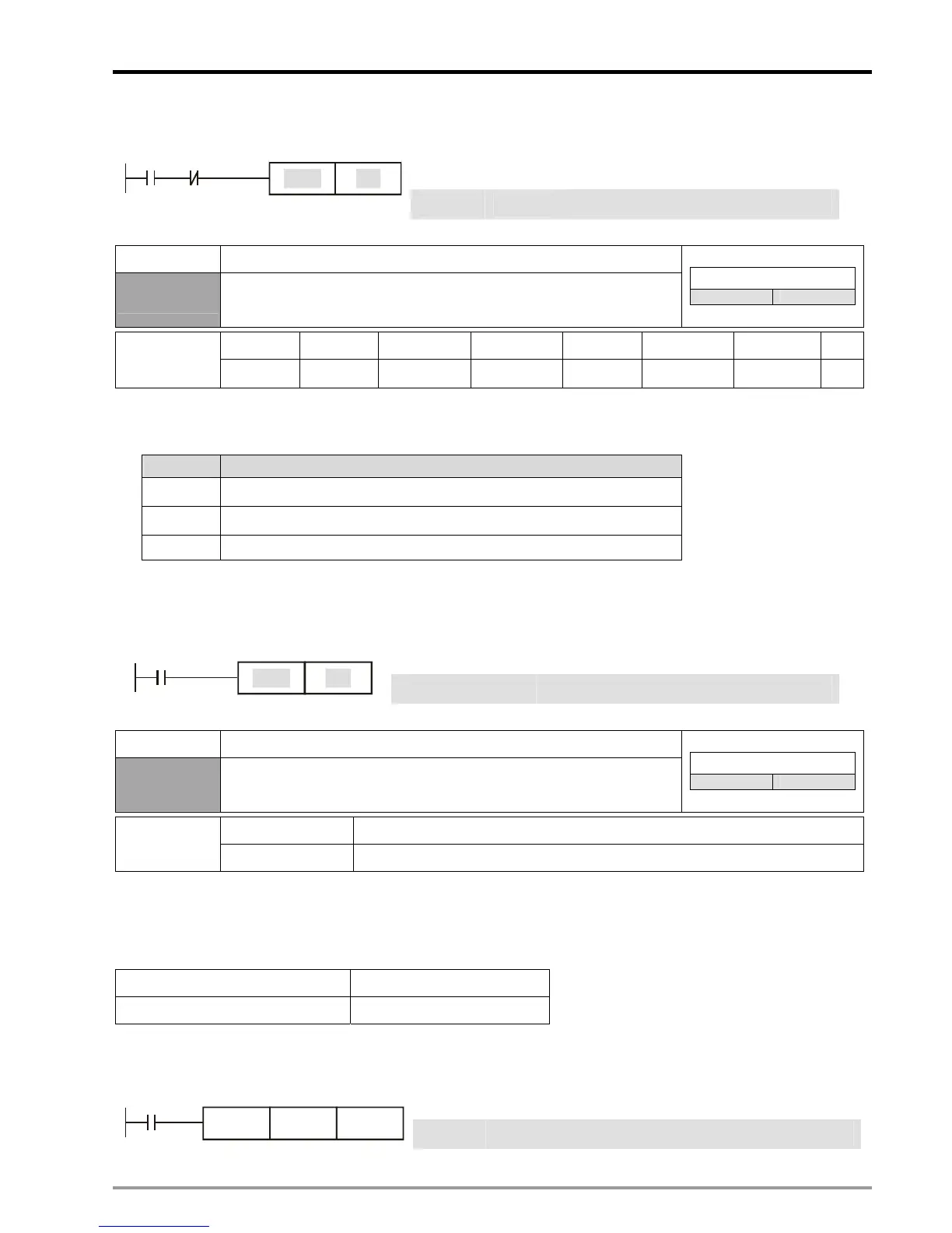
Ladder diagram: Instruction: Operation:
LD X0
Load NO contact X0
ANI Y0
Connect NC contact Y0 in series
X0 Y0
Y1
SET
SET Y1
Drive Y1 and latch the status
Mnemonic Function
RST
Resets contacts, registers or coils
Controllers
20PM 10PM
X0~X377 Y0~Y377 M0~M4095 S0~S1023 T0~T255 C0~C255 D0~D9999 V, Z
Operand
-
9 9 9 9 9 9 9
Explanations:
1. When RST instruction is driven, the actions of the designated devices are:
Device Status
S, Y, M Coil and contact are set to OFF.
T, C Current value is cleared. Associated contacts or coils are reset .
D, V, Z The content is set to 0.
2. Status of designated devices remains the same when RST instruction is not executed.
Program Example:
Ladder diagram: Instruction: Operation:
LD X0
Load NO contact X0
X0
Y5
RST
RST Y5
Reset contact Y5
Mnemonic Function
TMR
16-bit Timer
Controllers
20PM 10PM
T-K T0 ~ T255, K0 ~ K32,767
Operand
T-D T0 ~ T255, D0 ~ D9999
Explanations:
When TMR instruction is executed, the designated timer coil will be ON, and the timer will be enabled. When the set
value in the timer is reached (present value ≥ set value), the associated contact will be ON and act as follows:
NO (normally open) contact Current flows
NC (normally closed) contact Current blocked
Program Example:
Ladder diagram: Instruction: Operation:
LD X0 Load NO contact X0
X0
T5TMR
K1000
TMR T5 K1,000
Set value in timer T5 as K1,000

 Loading...


