2 Hardware Specifications and Wiring
DVP-PM Application Manual
2-5
Single-ended common point transistor
output
#1
Item
Spec
Low speed High speed
Single-ended common point
#1
relay output
delay time
ONOFF 30us
Over-current protection N/A
DVP-10PM
Item
Spec
Double-ended differential output
Single-ended common point
relay output
Maximum frequency 1 MHz 200 kHZ
Output indicator LED display; light on = ON, light off = OFF
Output point configuration Y10 ~ Y17 Y0 ~ Y3
Working voltage 5 VDC 5 ~ 30VDC
Max. output current 40 mA 40 mA
Isolation Line driver Photocoupler isolation
Resistive < 25 mA 0.5A/1 點 (4A/COM)
Inductive -- 12W (24 VDC)
Current spec.
Lamp -- 2 W (24 VDC)
OFFON
Max. output
delay time
ONOFF
0.2 us
Over-current protection N/A
#1: Y0 ~ Y7 on DVP20PM00D are relay output; FP2+, FP2- on DVP20PM00M are high-speed transistor output, Y2 and Y3 are
low-speed transistor output, Y4 ~ Y7 are relay output. Common point for Y0: C0; common point for Y1: C1; common point for Y2
and Y3: C2; common point for Y4~Y7: C3. Output points of DVP10PM are all high-speed transistor outputs, and Y0~Y3 can be
used as general output points.
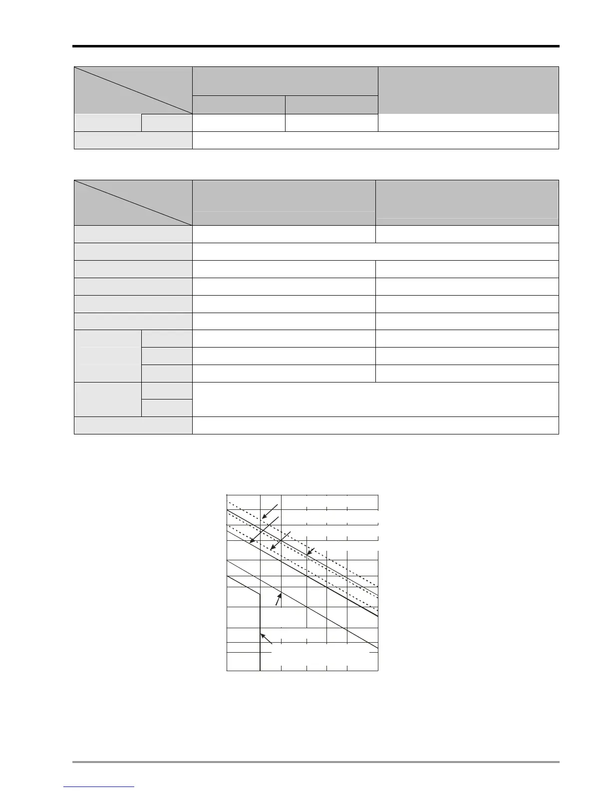
#2: The life cycle curve:
Contact
Current(A)
20
0.

 Loading...


