9 Electrical CAM
DVP-PM Application Manual
9-3
2. START0/PG0: Input terminal for enabling acyclic E-CAM
Ouput Terminals
1. FP0/RP0: Output terminal for pulse output of E-CAM. Max output frequency: 500kHz.
2. CLR0/CLR1: Output terminal for E-CAM synchronized output signal. When D1839, D1838 (PI) ≦
CP (Current Position) of Master (X axis) D1843,≦ D1842 (PII), CLR0/CLR1 will be ON. (For special
application of CLR0/CLR1, please refer to Reference function of synchronized output
in section 9.3.
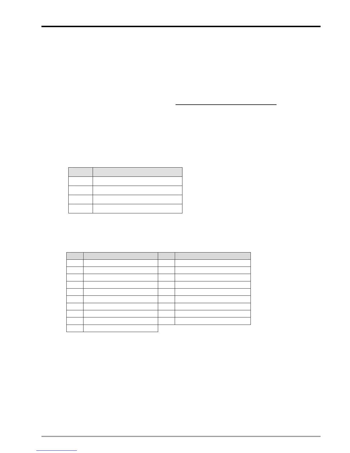
Input Terminal Polarity Setting
The polarity of input terminals is set by the corresponding bits of D1799. bit # = ON sets the input
terminal as NO contact while OFF sets the input terminal as the NC contact. For example, to set
MPGA0/MPGB0 as NO contacts, you have to set ON b1 and b2 of D1799, i.e. specify D1799 = 6.
D1799 (Input Terminal Polarity)
Bit# X-axis Input Terminal Polarity
0
PG0
1
MPGB0
2
MPGA0
7
START0
Input Terminal Digital Filter
D1806 High Byte: Filter coefficient of MPG0 / MPG1. D1806 Low Byte: Filter coefficient of other input
points other than X points. Filter frequency: 85000/2
N+4
(kHz).
N kHz N kHz
1 2656.25 11 2.593994
2 1328.125 12 1.296997
3 664.0625 13 0.648499
4 332.0313 14 0.324249
5 166.0156 15 0.162125
6 83.00781 16 0.081062
7 41.50391 17 0.040531
8 20.75195 18 0.020266
9 10.37598 19 0.010133
10 5.187988
9.2.1.3 Input/Output Pulse Type Setting
When Virtual Master is applied or the input pulses for Master are from Y axis of PM, settings of D1864
(MPG pulse input type) and D1816/D1896/D1976 (pulse output type) should match with each other, i.e.
if the source of Master is set as single phase (P/D), the output pulse type of Y axis should be single
phase as well. For wirings, simply connect MPGA0 (A0+, A0-) with Y axis output terminals (FP1+, FP1-)
and the setting is completed.

 Loading...


