9 Electrical CAM
DVP-PM Application Manual
9-28
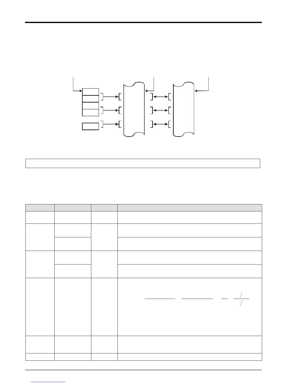
E-CAM data of 10,000 points and is set up by CR#0~9999. One set of E-CAM data consists of 2 points including
Master and Slave position, and the unit of every point is Dword. For example, 2 sets of E-CAM data include 4
Master/Slave points which requires 8 CRs as the below structure. In addition, for details about single-data real
time modification, please refer to 9.4.2.1.
D0
D1
D2
D3
...
D7
CR #0
CR #1
CR #2
CR #3
...
CR #7
M: Master position
S: Slave position
32 -bit instruction n=4 indicates 2 sets of CAM Data,
Specified CR
M0Low
M0High
S0Low
S0High
...
S1High
Corresponding
CAM Data
Specified devices
CR#10000: Create rotary cut E-CAM Data
[Explanations]
DVP-20PM provides CR#10000 exclusively for creating rotary cut E-CAM. The user can create and apply the
rotary-cut E-CAM by setting up the related machinery parameters according to actual needs. Parameters for
rotary-cut E-CAM are as below:
Parameters Data Format Explanations
P1
Length of
Master
Integer Length of the material feeding axis. Unit:mm
Length of Slave Length of the cutting axis (cutter length included). Unit: mm.
P2
Sync start
position
Integer
When sync function is enabled, the register sets up the sync start
position.
Length of sync
area
Length of sync area. Unit: mm.
P3
Sync end
position
Integer
When sync function is enabled, the register sets up the sync end
position.
P4
Magnification
ratio
Floating
point
The speed of master and slave is synchonized in sync area.
Calculation method of magnification ratio:
11
22
1
2
2
22
1
11
21
14.314.3
DR
DR
F
F
R
DF
R
DF
VV =⇒
××
=
××
⇒=
where,
V
1
(V
2
) = Master(Slave) speed (
mm
/
sec
);
F
1
(F
2
) = Master(Slave) frequency (Hz);
D
1
(D
2
) = Master(Slave) diameter;
R
1
(R
2
) = Master(Slave) pulses of single round.
P5
Max
magnification
ratio
Floating
point
P6
Acceleration Integer E-CAM acceleration setting:

 Loading...


