9 Electrical CAM
DVP-PM Application Manual
9-29
curve
(Low word)
0:const speed
1:const Acc
2:SingleHypot
3:Cycloid
CAM curve selection for different sections in sync area, e.g. start,
end:
0: leftCAM: Sync area is on the left side of CAM curve
1: midCAMall: Sync area is in the middle
2: midCAMbegin
3: midCAMend: (When the curve is selected, E-CAM stops
automatically when completed)
5: rightCAM: Sync area is on the right side of CAM curve.
Note: when CAM curve 2 or 3 is selected, the langth of Master will
be calculated by system.
CAM curve
(High word)
Integer
Sync area setting
b[13]=1: Create sync area setting. When the function is enabled, P2
and P3 should be filled with start and end position of sync area.
b[14]=1: Only single data real-time modification is applicable.
b[15]=1: Borrow the data setting of previous E-CAM
P7 Results Integer
Display the rotary cut E-CAM creating results (when read back):
0: OK
1: Input data is not proper
2: Insufficient length of E-CAM.
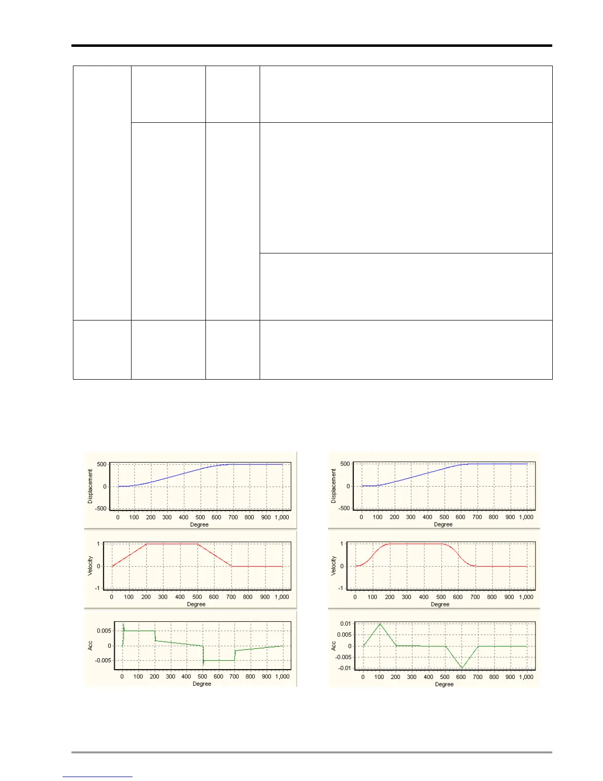
P6 sets up the rotary cut acceleration curves and the E-CAM curves, and the examples of each curve are as
below:
Acceleration curves
0: const speed
1: const Acc

 Loading...


