9 Electrical CAM
DVP-PM Application Manual
9-60
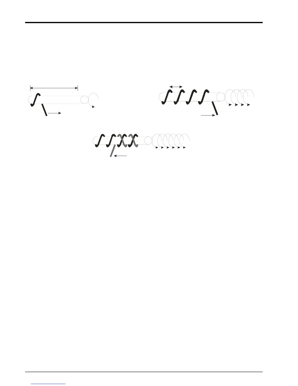
The movement of winding shafts and coil shafts are explained as below. The coil shaft (Slave) follows the winding
shaft (Master) and reciprocates within the range of single layer in certain proportion with winding shaft. At the
beginning, Slave starts at the left end and moves one coil space as diagram (A). When Slave moves to the right
end of the single layer range as indicated in disgram (B), the moving direction of Slave reverses as diagram (C).
When Slave reaches the left end of single layer range, the moving direction of Slave reverses again.
Range(rounds) of single layer
(A)
Total rounds of winding
Coil spacin
(B)
(C)
From the above winding movements, there are 3 major input parameters: 1. rounds per layer, 2. total rounds of
winding, and 3. coil spacing (The value of coil spacing is calculated by adding coil diameter with the space
between each round). In addition, Mechanical parameter (mm/pulses) is required for obtaining the Master/Slave
(winding shaft/coil shaft) proportion. Mechanical parameter consists of mechanism parameter and servo
parameter. Mechanism parameter is the the moving distance per round (mm/revolution) and servo parameter is
the pulses per round (pulses/revolution) obtained by multiplying the electronic gear ratio. Mechanism parameter
(mm/revolution) divided by servo parameter (pulses/revolution) equals the mechanical parameter (mm/pulses).
After the parameters are ready, apply cyclic E-CAM on X axis (Slave) because the coil shaft reciprocates cycle by
cycle, and single speed positioning on Y axis (Master) because the winding shaft moves on in the sme direction.

 Loading...


