9 Electrical CAM
DVP-PM Application Manual
9-61
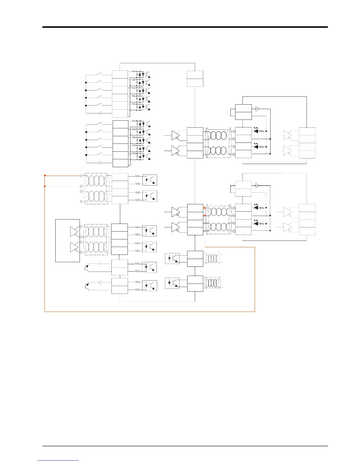
9.6.1.2 Hardware Wiring Diagram
LSP0
LSN0
Shielded cable
A0+
A0-
B0+
B0-
+24V
24V
0V
5-24VDC
+24V
PG 0+
5-24VDC
A phaseA
B phase
LSP1
LSN1
A1+
A1-
B1+
B1-
PG 1+
PG 0 -
PG 1-
FP 1+
FP 1-
RP 1+
RP 1-
CLR1+
CLR1-
START1
START0
STOP1
STOP0
FP 0+
FP 0-
RP 0+
RP 0-
/PLS
SIGN
/SIGN
PLS
VDD
COM+
24V
5-24VDC
ASDA series
CLR1+
CLR1-
5-24VDC
Master servo (winding shaft)
FP 1+
FP 1-
OA
/OA
OB
/OB
/PLS
SIGN
/SIGN
PLS
VDD
COM+
24V
ASDA series
OA
/OA
OB
/OB
DOG0
S/S0
DOG0
S/S0
Slave servo (coil shaft)
MPG pulses
Shielded cable
In above wiring diagram, we connect output terminal of Y axis (FP1+、FP1-) to the MPG input terminals (A0+、A0-)
as the source of Master. By this wiring method, winding operation of coil shaft (Slave) will not be influenced no
matter the winding direction of winding shaft (Master) is clockwise or counter-clockwise. Therefore, in this case we
only connect single direction for Master.
9.6.1.3 Create E-CAM Curve
After the wiring, create E-CAM Data in PMSoft as below.

 Loading...


