13 CANopen Communication Card
DVP-PM Application Manual
13-21
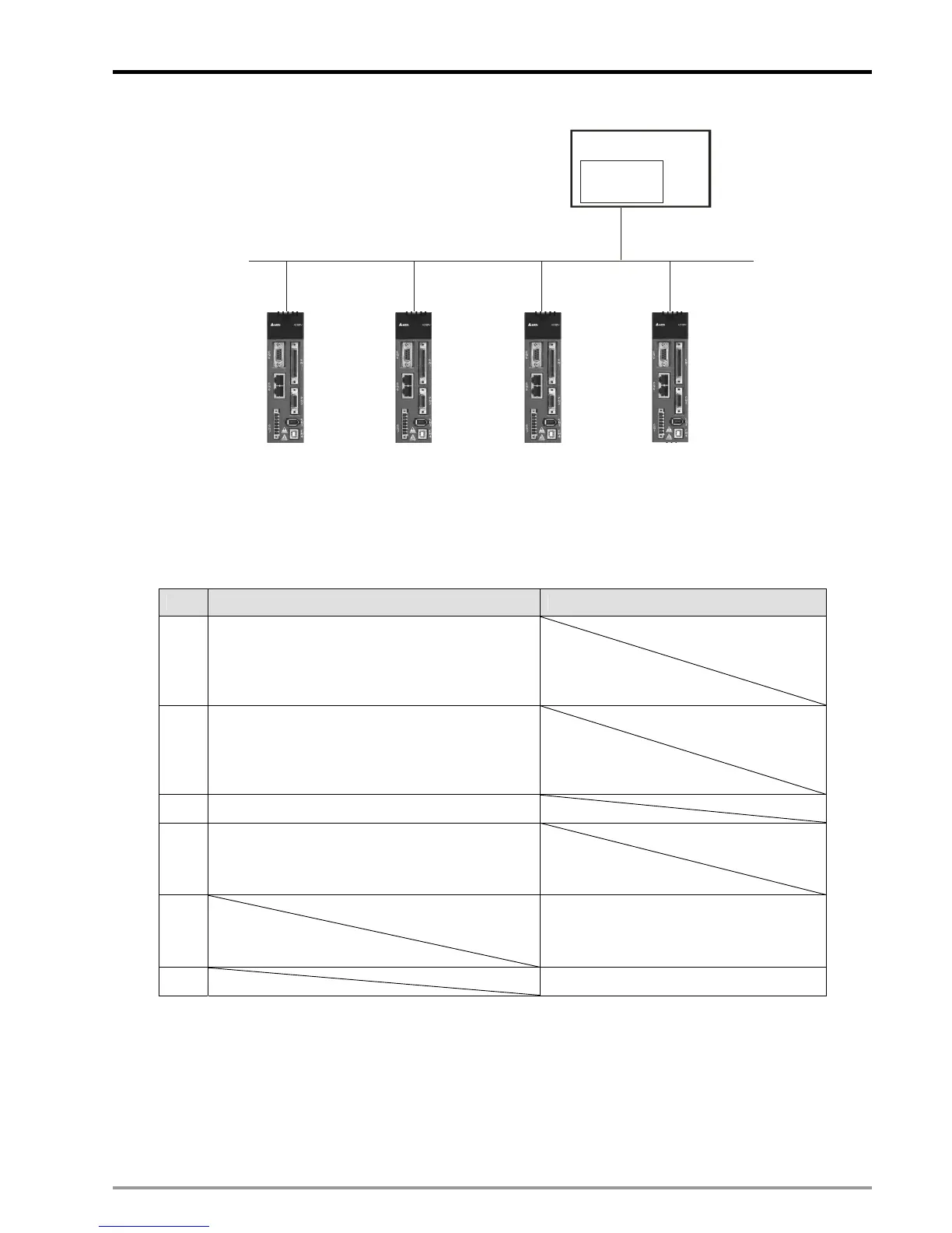
Canopen Network
FPMC
Node: 127
Node: 1
Node: 2
Node: 3Node: 4
20PM
Master
SlaveSlaveSlaveSlave
In A2 mode, there are 6 sets of PDOs for setting servo parameters. The user can monitor servo status
directly by accessing the control registers through CANopen network. Additional setting for PDO parameters
is not required. The PDO allocation for DVP-FPMC (Master) and servo drives (Slaves) is listed as the table
below: 4 sets of PDO for DVP-FPMC and 2 sets of PDO for servo data transmission.
PDO Master (transmit) Slave (receive)
1
Target position of profile position mode
(CRn70~CRn71)
Target speed of profile position mode
(CRn72~CRn73)
2
Acceleration time(ms) of profile position mode
(CRn74~CRn75)
Deceleration time(ms) of profile position mode
(CRn76~CRn77)
3 Servo drive control (CRn60)
4
Target position of interpolation position mode
(CRn90~CRn91)
Enable interpolation positioning (CRn92)
5
Servo drive status (CRn20)
Current operating mode of servo drive
(CRn21)
6 Servo drive position (CRn22~ CRn23)
A2 mode communication setting:
z ASDA-A2 settings
Before setting up CANopen connection, set the servo drives in CANopen mode by the following steps:
1. Set A2 Keypad P1-01as 0x0B(Set ASDA-A2 in CANopen mode)

 Loading...


