14 High Speed Compare and Capture
DVP-PM Application Manual
14-10
(1) Control registers: D3, D2 = H5004 Æ Data source: C204(Bit3-0=4); Enable Capture function
(Bit5-4=0); Trigger switch: X axis _DOG0(Bit15-12=5).
(2) Data registers: D5, D4 = K100 Æ can be specified with a random value.
Step 3: Set M2. Active Capture function by TO instruction
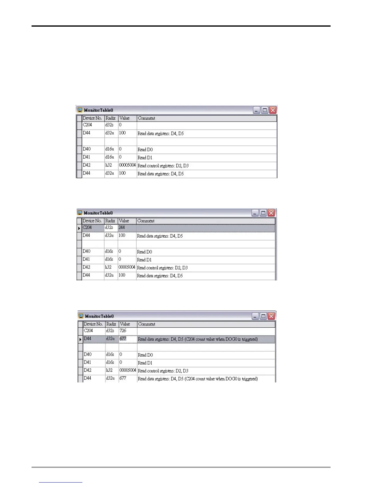
Step 4: Set M3. Read the data set up in D0~D5 as below:
Step 5: Set M4 to set C204 counting mode as P/D (Pulse/direction) then set M5 to enable C204.
Step 6: Rotate the MPG to check if C204 is counting as below.
Step 7: Keep rotating the MPG and trigger DOG0 to capture the data immediately.
Step 8: Set M3 to read the the caught value. D44 stores C204 count value when DOG0 is triggered.

 Loading...


