3 Functions of Devices in DVP-PM
DVP-PM Application Manual
3-12
32-bit High Speed Counter:
20PM:
C200, C204
1. The setup range of 32-bit high speed counter: K-2,147,483,648 ~ K2,147,483,647.
2. C200/C204 counting mode setting:
Counting mode
Counter
Device b0 / b1
Reset signal
(Valid only when b3 = 1)
Input signal
1
st
set C200 K1M1200 PG0 (M1203) A0+, A0-, B0+, B0-
2
nd
set C204 K1M1204
0: U/D*
1: P/D*
2: A/B*
(Single frequency)
3:4A/B
(Quadruple
frequency)
X11- (M1207) X2, X3, S/S
Note:
z U/D: Counting up / Counting down, P/D: Pulse / Direction, A/B: A-phase / B-phase
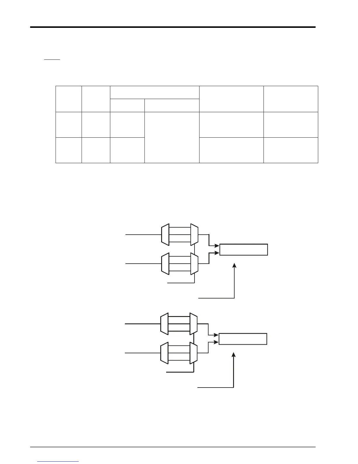
3. M1908: Input signal control of C200 / C204
When M1908 = OFF, the input signal of C200 is controlled by MPG A0/B0 and reset signal is controlled by
PG0. In addition, Input signal of C204 is controlled by MPG A1/B1 and reset signal is controlled by PG1.
C200
C200
reset signal
Counting mode selection
Input pulse
Input pulse
Puls
U
A
B
Dir
PV of C204
D
M1204/M1205
MPGB1
MPGA1
M1207=1, PG1
When M1908 = ON, the 3 axes X/Y/Z share the same high speed counter C200. The input signal of C200
is controlled by MPG A0/B0. C200 reset signal is controlled by PG0.

 Loading...


