U
A
B
Dir
PV of C200
D
M1200/M1201
MPGB0
MPGA0
M1203=1, PG0
4. SV can be K value (decimal) or D register (Special data register D1000~D2999 is not included). SV can be
a positive or negative value. If a D register is specified as SV, it will occupy 2 consecutive data registers.
5. PV in the general purpose counter will be cleared when power of DVP-PM is OFF. If the counter is a
latched (accumulative) type, PV and the contact status will be retained, and PLC will resume counting after
power is ON again.
6. When PV reaches up to 2,147,483,647, the next PV will turn to -2,147,483,648. When PV reaches down
to -2,147,483,648, the next PV will turn to 2,147,483,647.
10PM:
C200, C204, C208, C216, C220
1. The setup range of 32-bit high speed counter: K-2,147,483,648 ~ K2,147,483,647.
2. C200/C204/C208/C216/C220 counting mode settings:
Counting mode
Counter
Device b0 / b1
Reset signal Reset
terminal
Input signal
1
st
set C200 K1M1200 M1203 X10 X0, X1, S/S
2
nd
set C204 K1M1204 M1207 X11 X2, X3, S/S
3
rd
set C208 K1M1208 M1211 X12 X4, X5, S/S
4
th
set C212 K1M1212 M1215 X13 X6, X7, S/S
5
th
set C216 K1M1216 M1219 X0 X10+, X10-, X11+, X11-
6
th
set C220 K1M1220
0: U/D*
1: P/D*
2: A/B*
(Single
frequency)
3:4A/B
(Quadruple
frequency)
M1223 X1 X12+, X12-, X13+, X13-
Note:
z U/D: Counting up / Counting down, P/D: Pulse / Direction, A/B: A-phase / B-phase
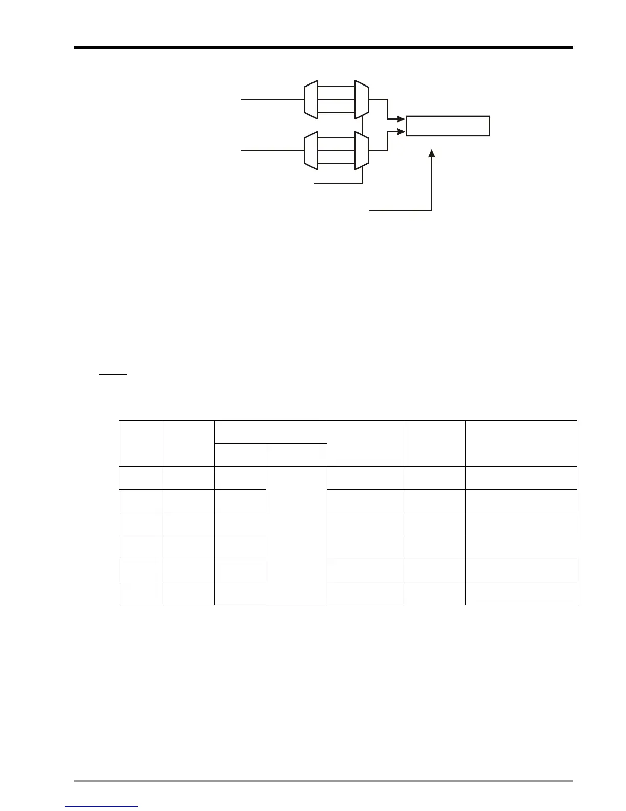
3. Operation diagram:
z Counting mode of C200 is selected by M1200/M1201. Input signal of C200 is controlled by X0/X1.
Reset signal of C200 is enabled by M1203 and triggered by X10.

 Loading...


