3 Functions of Devices in DVP-PM
DVP-PM Application Manual
3-42
C208 K10
M1
K4
K1M1208MOVP
DCNT
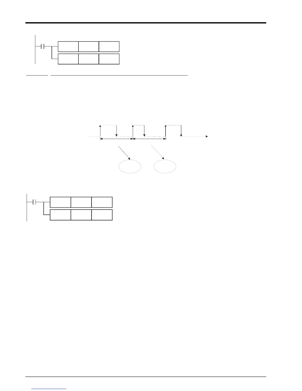
Example 2
: Use the 3
rd
set of timer and set up the timing mode as Cycle mode:
1. In O100 main program, design the 3
rd
set of high speed timer with cycle timing mode by setting K1M1208 = K5,
i.e. b0 = 1, b2 = 1.
2. Execute the program and C208 will start to time the interval between rising edges of the start signal X12. The
timed interval will be stored in C209 with the timer resolution 0.01us. Please see the below diagram for the timing
diagram:
t1 t2
X12
t
C209 C209
Cycle mode. Unit: 0.01μs
The example program of step 1 and step 2 is as below:
C208 K10
M1
K5
K1M1208
MOVP
DCNT
3. Cycle mode is mainly used in frequency measuring application.
Function Group:
I/O Modules Detection
Number:
D1140, D1142, D1143
Explanations:
D1140: Number of right-side modules (AIO, PT, TC, etc.), max. 8 modules can be connected.
D1142: Number of input points (X) on DIO modules.
D1143: Number of output points (Y) on DIO modules
Function Group:
Setting Up Latched Area
Number:
D1200 ~ D1211
Explanations:
1. The specified range between D1200 (start) and D1211 (end) will be set up as the latched area of DVP-PM.
2. Please refer to the tables in 3.1 for more details.
 Loading...


