3 Functions of Devices in DVP-PM
DVP-PM Application Manual
3-43
Function Group:
Enabling force-ON/OFF of input point X
Number:
M1304
Explanations:
When M1304 = ON, the peripheral devices, e.g. PMSoft, can force input ponts X0~X17 to be ON/OFF. However, the
LED will not respond to the ON/OFF state in this case.
Function Group:
ID of right-side modules
Number:
D1320 ~ D1327
Explanations:
1. When I/O modules are connected, the ID of each I/O module will be stored in D1320~D1327 in connection order.
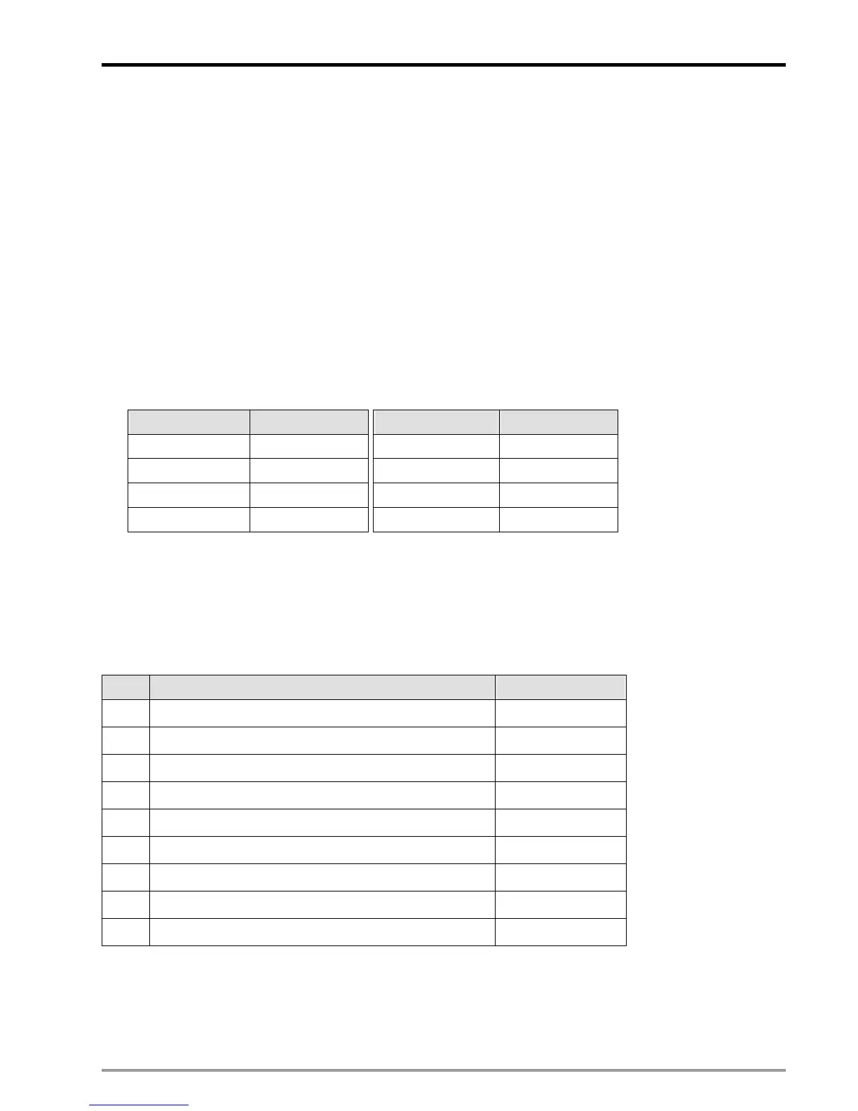
2. ID of Special I/O modules for DVP-PM:
Module Name Module ID (hex) Module Name Module ID (hex)
DVP04AD-H2 H’6400 DVP01PU-H2 H’6110
DVP04DA-H2 H’6401 DVP04PT-H2 H’6402
DVP04TC-H2 H’6403 DVP06XA-H2 H’6604
DVPPM H’6260 DVP01HC-H2 H’6120
Function Group:
Interruption
Number:
D1400, D1401
Explanations:
1. To enable the interrupts below, please set ON the corrensponding bits of D1400.
bit# Interruption No.
0 Timer interrupt
I0
1 External interrupt Start0 / X0*
I1
2 External interrupt Stop0 / X1*
I2
3 External interrupt Start1 / X2*
I3
4 External interrupt Stop1 / X3*
I4
5 External interrupt X4*
I5
6
External interrupt X5*
I6
7
External interrupt X6*
I7
8
External interrupt X7*
I8
Note: X0*~X7* are applicable only for DVP-10PM
2. If timer interruptipon is enabled, please enter the interrupt interval in D1401
3. There 2 types of interrupts including external interrupt and timer interrupt:
External interrupt: When the external terminal is triggered by the rising/falling edge of an input signal, the
current executing program will be interrupted and the interrupt subroutine will be executed immediately
 Loading...


