Chapter 7 Optional AccessoriesME300
(2) In the bottom right-hand corner of the Editor, click the page number to edit, or on the View menu, click
HMI Page to start editing the main page. As shown in the picture above, the following objects are
available. From left to right they are: Static Text, ASCII Display, Static Bitmap, Scale, Bar Graph, Button,
Clock Display, Multi-state bit map, Units, Numeric Input, the 11 geometric bitmaps, and lines of different
widths. Use the same steps to add Static Text, Static Bitmap, and geometric bitmaps as for the Start-up
page.
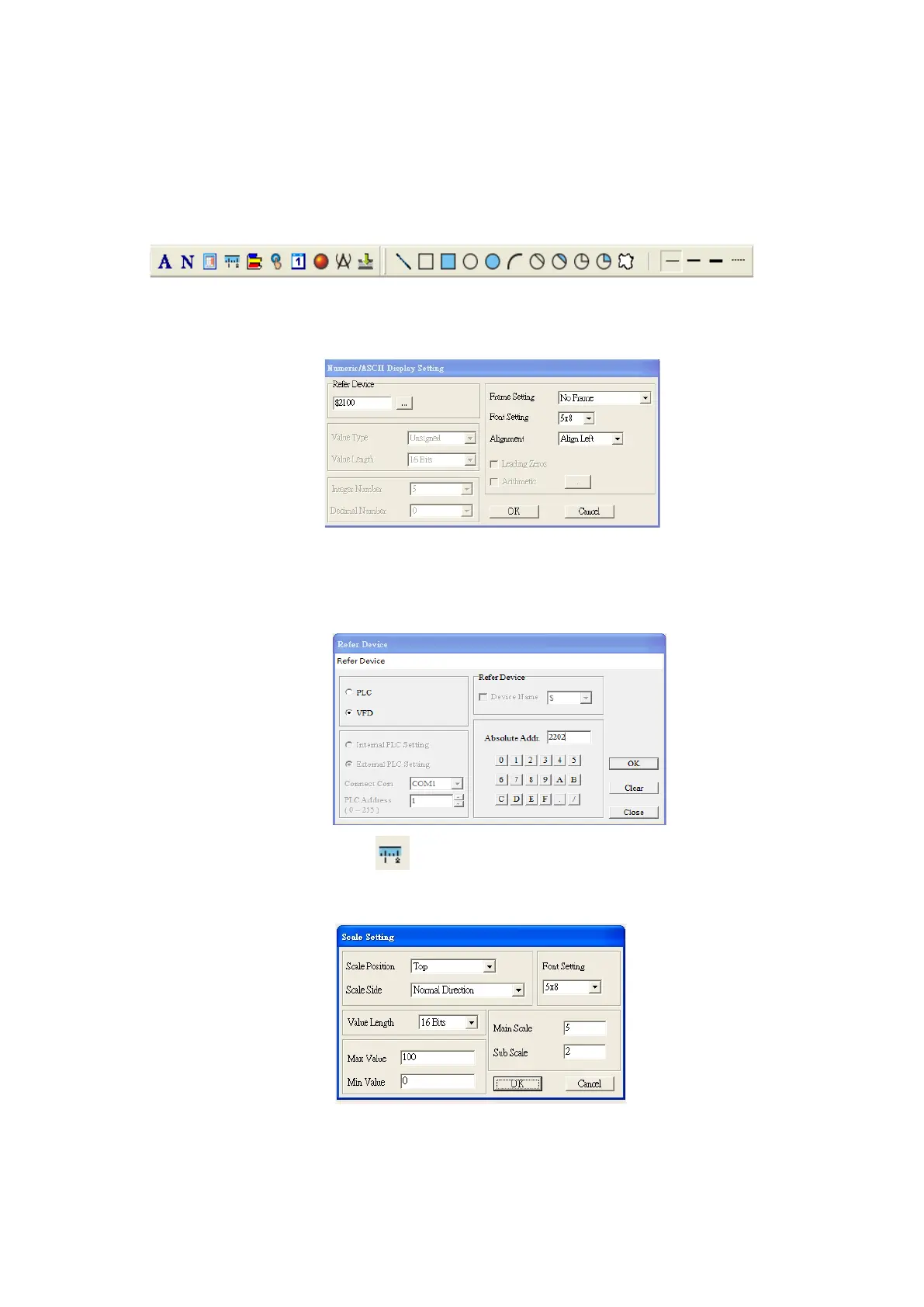
(3) Add a numeric/ASCII display. On the toolbar, click the Numeric/ASCII button. In the page, double-click
the object to specify the Refer Device, Frame Setting, Font Setting and Alignment.
Click […]. In the Refer Device dialog box, choose the VFD communication port that you need. If you
want to read the output frequency (H), set the Absolute Addr. to 2202. For other values, refer to the
ACMD Modbus Comm Address List (see Pr.09-04 in Chapter 12 Group 09 Communication Parameters).
(4) Scale Setting. On the toolbar, click to add a scale. You can also edit the Scale Setting in the
Property Window on the right-hand side of your computer screen.
A. Scale Position: specifies where to place the scale.
B. Scale Side: specifies whether the scale is numbered from smaller numbers to larger numbers or
from larger to smaller.
C. Font Setting: specifies the font.

 Loading...


