Chapter 15 Safe Torque Off Function
ME300
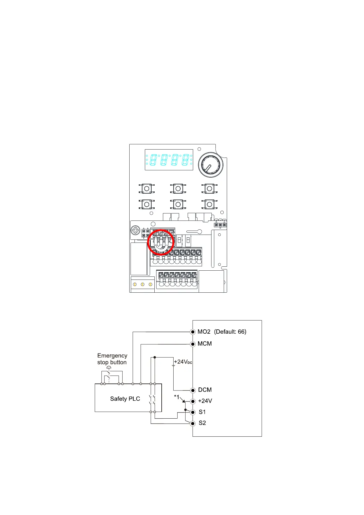
15-3 Wiring Diagram
15-3-1 Figure 2 shows the internal circuit diagram of the safe control loop.
15-3-2 The terminals of the safe control loop +24V-S1-S2 are short-circuited together with jumper wire
at the factory, as shown in Figure 2.
15-3-3 The safe control loop wiring diagram is as follows:
1. Remove the jumper wire from +24V-S1-S2.
2. The wiring is shown in Figure 3 below. Normally, you must close the ESTOP contact switch,
so the drive can output without displaying an error.
3. In STO mode, the switch ESTOP is turned on. The drive stops outputting and the keypad
displays STO.
Figure 15-2
Figure 15-3
N
OTE
*1 is factory jumper wire shorting +24V-S1-S2. To use the Safety function, remove this jumper wire.
To disable the Safety function, short-circuit +24V-S1-S2 with a jumper wire.

 Loading...


