Chapter 5 Main Circuit TerminalsME300
5-1 Main Circuit Diagram
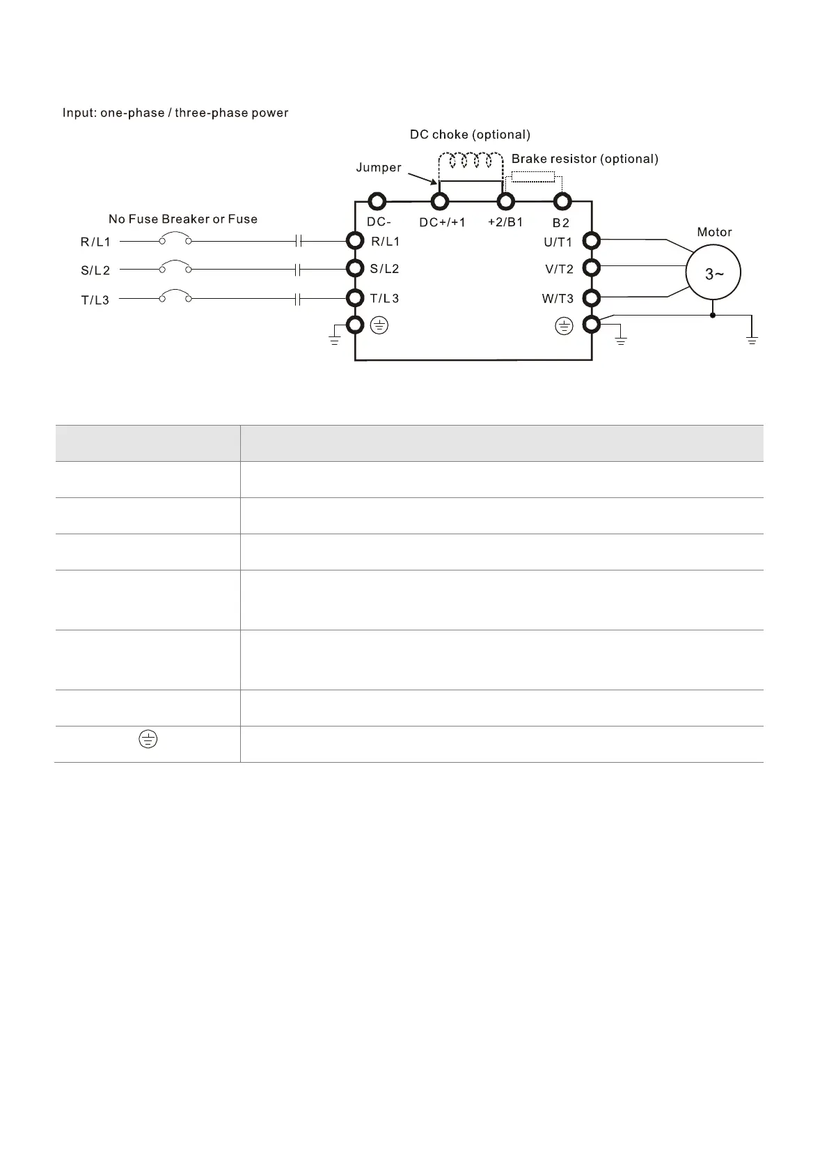
Figure 5-5
Terminals Descriptions
R/L1, S/L2 Mains input terminals one-phase
R/L1, S/L2, T/L3 Mains input terminals three-phase
U/T1, V/T2, W/T3 Motor output terminals for connecting three-phase
IM and PM motors
+1, +2
Connections for DC reactor to improve the power factor and harmonics.
Remove the jumper when using a DC reactor.
DC+, DC-
Connections for brake unit (VFDB series)
Common DC BUS
B1, B2 Connections for brake resistor (optional). Refer to Section 7-1 for details.
G
round connection; comply with local regulations.
Table 5-1

 Loading...


